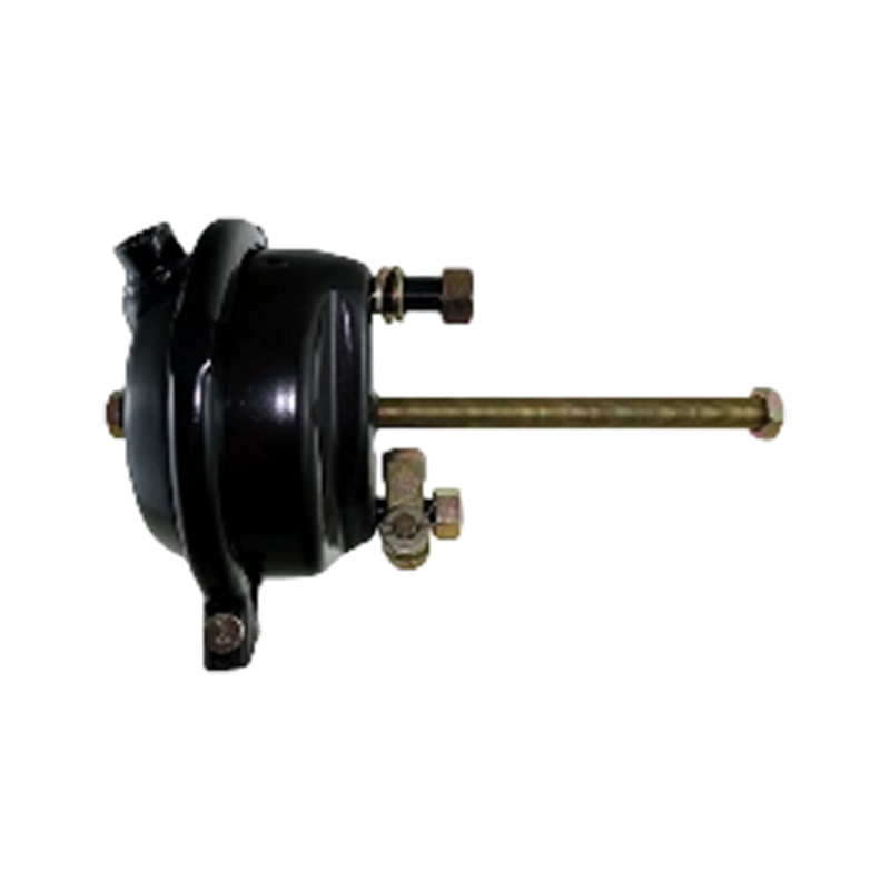
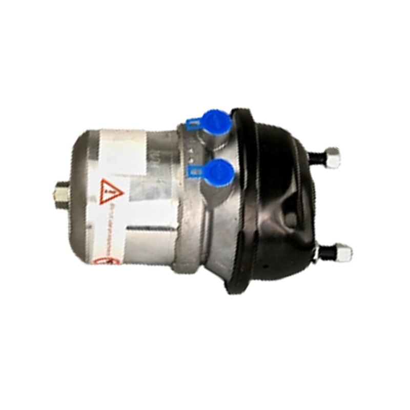
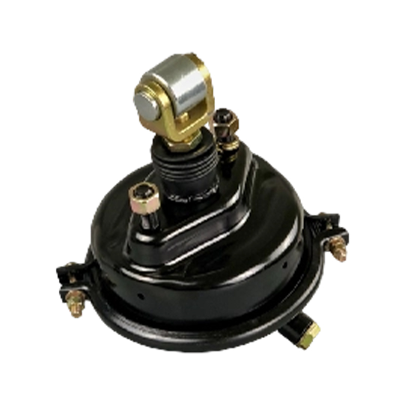
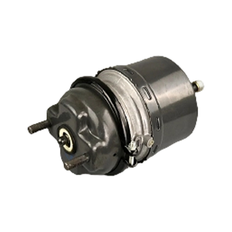

A spring brake chamber is a combined pneumatic actuator fitted to the drive axle, and often the trailer axles, of a heavy duty truck. It houses two separate diaphragms in one body: a service brake section that applies the brake using air pressure in the normal way, and a spring brake section behind it that applies the brake mechanically using a powerful compressed spring whenever air pressure is removed, providing both the parking brake and an emergency backup if the service air supply is lost.
Two functions are combined in one unit because they need to act on the same brake linkage but under opposite logic. The service brake must apply when the driver presses the pedal and air pressure rises. The parking and emergency brake must apply when air pressure is absent, so that a vehicle with no engine running, or one that has suffered an air system failure, still comes to a safe stop and stays there. The spring brake chamber achieves both with one push rod acting on the same slack adjuster and foundation brake.
Two Chambers, One Push Rod
The chamber is built in two sections joined by a common wall. The front, service section works like a simple diaphragm brake chamber: air pressure from the foot brake valve pushes a diaphragm and push rod outward to apply the brake, and a return spring retracts it when pressure is released. The rear, spring section contains a large coil spring compressed behind its own diaphragm. As long as air pressure holds that spring compressed, it has no effect on the push rod. Removing that air lets the spring extend, driving the same push rod outward and applying the brake mechanically, independent of the service air supply.
Caging the Spring Safely
Because the spring brake section can exert very high force, and because it applies automatically whenever air is lost, spring brake chambers include a mechanical release tool, sometimes called a caging bolt or release stud. This tool lets a technician manually compress the spring using a bolt through the rear of the chamber, so the brake can be released for towing or bench work when air pressure is not available. Using this tool incorrectly, or attempting to disassemble a charged spring brake chamber without it, is a well-known cause of serious workshop injury, since the stored spring energy is very large.
Parking Brake and Emergency Function
In normal parking use, the driver's hand brake valve exhausts air from the spring section, allowing the spring to apply the brake at will. In an emergency, such as a supply line failure, the same thing happens automatically as pressure is lost, without any driver action, which is why spring brake chambers are central to the fail-safe design of air brake systems on heavy vehicles.
Sizing and Stroke
Spring brake chambers are described by two numbers, roughly corresponding to the effective area of the service section and the spring section, for example 30/30 or 24/30. Larger service sections give more braking force for a given pressure; larger spring sections give a stronger parking and emergency application. The chamber's stroke, how far the push rod travels, must also match the slack adjuster and foundation brake geometry, and this is checked as part of routine brake adjustment.
Common Failure Modes
Corrosion inside the housing, often from moisture in the air supply, is the most frequent cause of spring brake chamber failure, leading to diaphragm perforation, a weakened or broken spring, or a stuck push rod. External signs include a chamber that will not release the parking brake, one that leaks air continuously from a small breather hole, or uneven push rod travel compared with other chambers on the vehicle.
Matching a Replacement Chamber
Match the chamber size designation, the mounting bolt pattern (commonly a standard bolt circle), the push rod length and thread, and the port thread for both the service and spring sections. Confirm whether a manual release stud is required as standard on your fleet's specification.
- Fit point: drive axle and trailer axle brake assemblies
- Function: service braking plus spring-applied parking and emergency braking
- Construction: two diaphragms sharing one push rod
- Safety feature: manual spring release tool
- Sizing: described by service/spring area, e.g. 30/30
- Service parts: diaphragms, springs, release kits, complete chambers