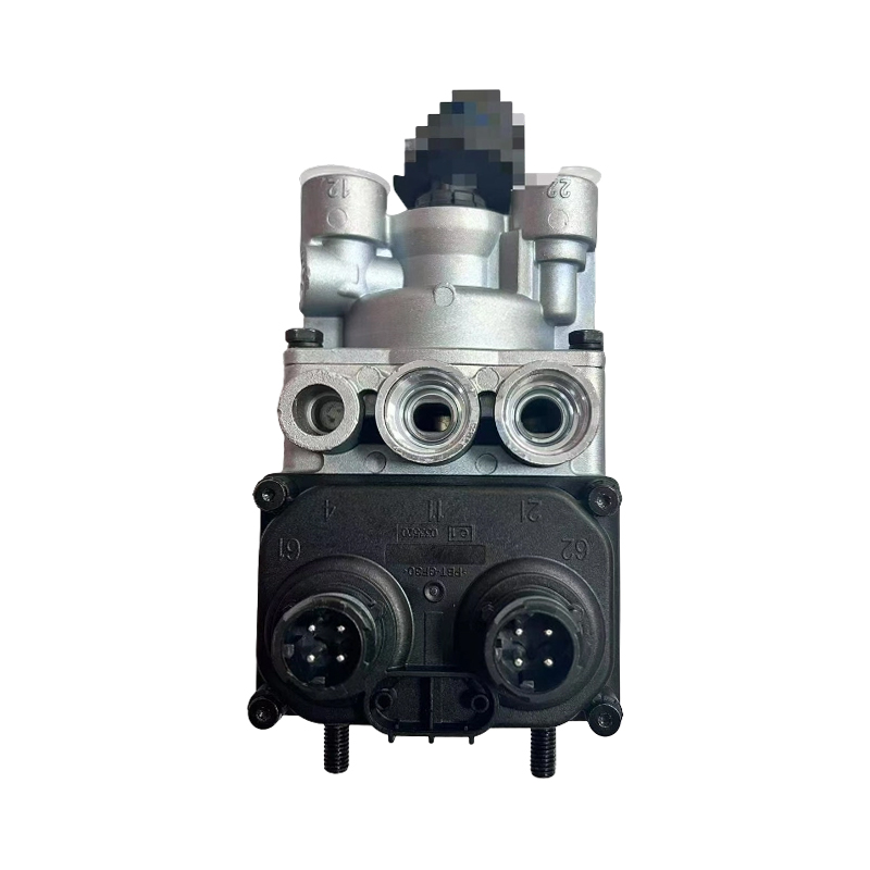
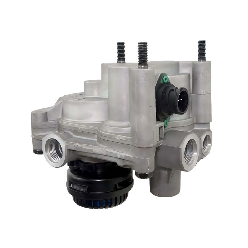
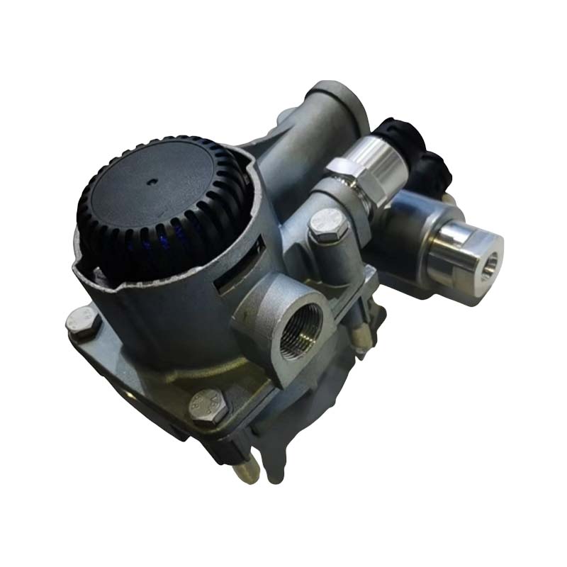
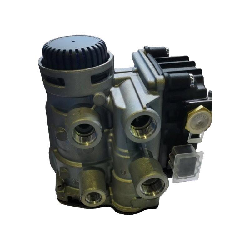
A dual circuit foot brake valve assembly is the pedal-operated control valve of a truck or bus air brake system. It converts the driver's pedal movement into a graduated air pressure and delivers that pressure to two separate brake circuits at the same time, usually the front axle circuit and the rear axle circuit. Each circuit has its own supply and its own piston stage, so a failure in one circuit does not remove braking from the other.
Every time the driver presses the brake pedal on an air-braked vehicle, something has to decide how much air reaches the brake chambers. That decision cannot be an on-off switch. The driver needs to apply a little brake pressure for a gentle stop and a lot for an emergency stop, and to feel the difference through the pedal. The dual circuit foot brake valve is the component that turns a few centimetres of pedal travel into a precise, proportional air pressure, while keeping two circuits fully independent for safety.
Two Circuits, Two Piston Stages
Inside the housing sit two pistons working in series, a primary piston that controls one circuit and a secondary piston that controls the other. Pedal force pushes the primary piston, which opens its own inlet seat and delivers air to its circuit. The pressure produced also acts on the secondary piston and moves it to open the second inlet seat, so both circuits are supplied almost together. Each circuit draws air from its own reservoir through its own supply port.
What Happens When One Circuit Fails
If one circuit loses air, the valve does not lose control of the other. A mechanical linkage between the two pistons still lets the pedal force move the healthy piston directly, so the driver can still apply the remaining circuit, although with a longer pedal travel and some loss of braking force. This built-in fallback is the core reason air braked vehicles use a dual circuit valve in place of a single-circuit design.
Graduated Control and Pedal Feel
The valve works on a balance principle. As delivery pressure rises, it acts on a reaction piston and pushes back against the pedal, so the driver feels the braking force through the pedal. A calibrated spring stack sets how much pedal effort is needed for each bar of pressure. When the driver holds the pedal, the valve closes both the inlet and exhaust seats and holds the pressure steady, and when the pedal is released the exhaust seat opens and the circuits are vented through the exhaust port.
Floor-Mounted and Suspended Pedal Types
Floor-mounted valves carry a pedal plate fixed to the top of the valve and are common on modern cab-over trucks. Suspended pedal types use a hanging lever that acts on the valve plunger through a roller or a push rod. The two types produce the same pressure but have different pedal geometry, so a floor-mounted valve cannot be fitted where a suspended type was specified without changing the pedal assembly.
Electrical Functions and Pedal Sensing
Most valves carry one or two stop-light switches that close when pedal pressure builds. On vehicles with electronic braking systems, a pedal valve version with an integrated sensor reports pedal travel or pressure to the brake controller, while the pneumatic circuits stay in place as a backup. The switch or sensor connector is therefore as important as the port layout when matching a replacement.
Matching the Pedal Valve to the Cab
Match the mounting type, the pedal plate or plunger geometry, the supply and delivery port threads, the stop-light switch or sensor, and the OEM number. A pedal valve that is close but not exact can change pedal height and travel, which affects both safety and driver comfort.
- Fit point: cab floor or pedal bracket
- Function: proportional control of two brake circuits
- Internal parts: primary and secondary pistons, reaction piston
- Port layout: two supply, two delivery, one exhaust
- Electrical options: stop-light switch or pedal sensor
- Service parts: repair kit, pedal plate, seals, roller