


 Français
 Español
 中文简体
 русский

Gongzheng
Gongzheng
Gongzheng
Gongzheng
Gongzheng
Gongzheng
Gongzheng
Gongzheng
Gongzheng
Gongzheng
Gongzheng
Gongzheng
Gongzheng
Gongzheng
Gongzheng
Gongzheng

Content
- 1 The verdict first: what a passing result actually looks like
- 2 Before the clock starts: preparation that prevents a false pass
- 3 Running the test, step by step
- 4 Reading the result by circuit, not by component
- 5 Components that most often cause a failed test
- 6 Why 3 psi and 4 psi are not arbitrary numbers
- 7 Conditions that distort a leak-down reading
- 8 Tools that shorten diagnosis
- 9 Building the test into a preventive maintenance schedule
- 10 Mistakes that make a good test meaningless
- 11 Questions that come up on the workshop floor
- 11.1 Can I do a leak-down test on my own?
- 11.2 How long should the whole test take?
- 11.3 My truck passes the static test but fails the applied test. What does that mean?
- 11.4 Is a 2 psi loss in one minute acceptable on a combination?
- 11.5 Does the engine need to be running during the test?
- 11.6 How do European and American tolerances compare in practice?
- 11.7 What if the vehicle passes but the driver still reports slow pressure build-up?
A 6×4 tractor that loses more than 2 psi (roughly 0.14 bar) in one minute with the engine off will not pass a roadside inspection, no matter how new the brake linings are. That single number is what the whole leak-down test exists to produce. Everything else — charging the system to governor cut-out, holding the treadle down for three minutes, spraying soapy water on every fitting — is only there to explain why that number came out the way it did.
A complete test takes about 12 to 15 minutes on a properly equipped bay, and one technician can run it alone once the wheels are chocked. Below is the sequence in the order it should be performed, followed by the tolerances that decide pass or fail.
The verdict first: what a passing result actually looks like
Start with the limits, because most failed tests are failed before anyone picks up a spray bottle. The reference figures used in North American roadside inspection practice are stated as allowable pressure loss over a fixed hold time, separately for a single unit and for a tractor-trailer combination.
| Test stage | Single unit (truck or tractor alone) | Combination (tractor + trailer) | Hold time |
|---|---|---|---|
| System charged to governor cut-out | Typically 115–125 psi (7.9–8.6 bar) | Typically 115–125 psi (7.9–8.6 bar) | Until compressor unloads |
| Static test, brakes released | Maximum 2 psi loss | Maximum 3 psi loss | 1 minute |
| Applied test, service brake held | Maximum 3 psi loss | Maximum 4 psi loss | 3 minutes |
| Low-pressure warning | Must activate before 60 psi | Must activate before 60 psi | Static check |
| Spring brake emergency application | Must apply between 20 and 45 psi | Must apply between 20 and 45 psi | Static check |
European practice expresses the same idea differently. ECE R13 and the service literature of the major European truck builders usually talk in bar over a longer window — figures such as 0.1 to 0.5 bar over ten minutes, depending on which circuit is being measured and whether the engine is running. A tractor with a European air management unit and an American-style dash gauge will therefore need two numbers in your workshop, not one.
The practical rule: if the vehicle carries a specification plate or a workshop manual, its number wins. If it does not, use the table above and record the result on the job card so the next technician has a baseline to compare against.
Before the clock starts: preparation that prevents a false pass
Half of all confusing leak-down results come from the setup, not the test. A system that is still cooling down reads high; a system tested on an incline reads low; a system tested with the park brake set is not being tested at all in the way the standard intends.
What you need on the floor
- A calibrated pressure gauge — the dash gauge is for the driver, not for certification. A 0–150 psi glycerine-filled gauge with 2 psi graduations is enough for most work.
- A stopwatch or phone timer. Counting in your head is the single most common source of bad numbers.
- A spray bottle of soap solution — roughly one part dish soap to four parts water. Too much soap leaves a film that hides the next leak.
- Wheel chocks and a torch. A leak behind a chassis crossmember is invisible without light.
- Optional but useful: an ultrasonic leak detector for lines you cannot reach, and an inline flow meter if you are chasing a slow, distributed loss across a whole fleet.
Vehicle conditions that must be met first
- Park on level concrete, chock the wheels, and release the parking brake so the spring chambers are not held in the applied position — that would mask the very leak you are hunting.
- Run the engine until the compressor reaches governor cut-out and the dryer purges. This also warms the air in the system, which removes most of the false "pressure drop" caused by cooling.
- Shut the engine down. Switch the ignition back on so the low-pressure warning and gauges stay live, but do not restart.
- Wait 30 to 60 seconds for the pressure to stabilise. The reading will usually fall a little at this point as the warm charge equalises; that drop is not a leak and must not be counted.
- Confirm the system pressure at the start of the timed run. A test started at 90 psi is not comparable with one started at 120 psi, because leak rate scales with pressure.
Running the test, step by step
Step 1 — Establish the reference pressure
With the compressor unloaded and the engine off, note the gauge value. On most heavy trucks this sits between 115 and 125 psi; some European platforms cut out nearer 8 to 8.5 bar. Write this number down. Every subsequent reading is compared against it, and a two-minute argument with a driver is usually settled by producing the starting figure on paper.
Step 2 — The static test, brakes released
Start the timer and watch the gauge for exactly 60 seconds. Do not touch the pedal. On a single unit the loss must stay at or below 2 psi; on a tractor-trailer combination it must stay at or below 3 psi. A combination gets the extra 1 psi because it carries roughly twice the pipe volume, twice the fittings and an additional set of couplers — the allowance reflects geometry, not a weaker standard.
This is the stage where a failing truck shows its hand. A loss of 5 psi in a minute on a solo tractor points at something reasonably large: a service chamber diaphragm, a relay valve exhaust seat, a dryer purge valve that never fully closed, or an unloader stuck slightly open.
Step 3 — The applied test, service brake held
Press and hold the foot valve fully. Hold it for three minutes without releasing. Loss must not exceed 3 psi on a single unit and 4 psi on a combination. The applied test loads the whole service circuit, so it exposes splits that the static test misses — a hairline crack in a treadle valve body, a warped relay valve diaphragm, a chamber that only leaks when the pushrod extends.
Keep the pedal pressure steady. Riding the pedal up and down changes the volume in the circuit and produces readings that are not comparable with the standard.
Step 4 — Split the combination
If the combination fails but you do not yet know which half is responsible, uncouple the trailer supply line and cap the tractor coupling. Repeat both tests on the tractor alone. Then charge the trailer from a shop supply and repeat on the trailer alone. This split costs about four minutes and often saves an hour of guessing.
Note the coupling seals while you are there. Gladhand seals are one of the most frequently replaced parts in a fleet and one of the most frequently overlooked during a leak-down test, because the leak only appears when the lines are connected and under pressure.
Step 5 — Park and emergency circuit
Apply the parking brake control and observe. The spring brake circuit is a separate volume and has its own leakage behaviour. On most platforms a loss above about 4 psi over three minutes on the park circuit indicates a failed park valve seat, a leaking spring chamber, or a shuttle valve that is not seating.
While the system is charged, confirm the low-pressure warning activates before 60 psi, and that the spring brakes apply between 20 and 45 psi when pressure is bled down. These two checks are part of the same inspection in most jurisdictions and cost almost no extra time.
Step 6 — Localise with soap solution
Only now is it worth getting wet. Work from the compressor forward: discharge line, dryer inlet, dryer purge port, governor, unloader, then every push-to-connect fitting and threaded union in the supply circuit. Then move to the service circuit — foot valve body and exhaust, relay valves, quick release valves, ABS or EBS modulators, chamber clamp bands and diaphragm housing joints.
A leak that produces a visible bubble within three seconds is significant. A leak that produces a slow, creeping foam is worth noting but rarely explains a failed test on its own. Chase the fast bubbles first.
Reading the result by circuit, not by component
Once the number is on paper, the fastest way to the faulty part is to think in circuits rather than in parts. Each circuit fails in a recognisable way.
Supply and treatment circuit
Compressor, discharge line, air dryer, purge valve, governor and unloader. Failures here usually show up on the static test with the brakes released, and they often rise with temperature because a seal that is marginal when cold opens up when warm.
Service circuit
Foot valve, relay valves, quick release valves, ABS/EBS modulators and service chambers. These typically fail the applied test but pass the static one, because the leak only appears when pressure is commanded downstream.
Park and emergency circuit
Park valve, spring brake control valve, anti-compounding valve and spring chambers. Often shows as a slow continuous loss and a vehicle that creeps or fails to hold on a gradient.
Trailer circuit
Couplings, gladhand seals, trailer control valve, emergency relay valve and trailer chambers. Almost always the reason a combination fails while the tractor alone passes.
Suspension and auxiliary circuit
Levelling valves, lift axle valves and air suspension bellows share the same compressed air source on many tractors. A levelling valve that never fully closes will pull the whole system down slowly and look like a brake fault.
Air-operated accessories
Gearbox shift valves, clutch boosters, cab suspension and horn valves all tap the same supply. Every one of them is a potential contributor and every one is routinely ignored during a brake-only investigation.
This circuit-first view matters because the repair decision depends on it. A 3 psi loss traced to a levelling valve is a completely different commercial outcome from a 3 psi loss traced to a treadle valve, even though the gauge reads the same.
Components that most often cause a failed test
Across fleets running mixed European and American platforms, a predictable set of parts accounts for the majority of failures. Knowing them shortens diagnosis and also shapes what you keep on the shelf.
Air dryers and desiccant cartridges
A dryer that is not fully purging passes air slowly back through the purge port and shows up as a continuous small loss that never quite settles. Saturated desiccant makes it worse, because the moisture carried downstream attacks valve seats and accelerates corrosion in the very circuits you are testing. Cartridge condition and purge valve seating are worth checking before any deeper diagnosis.
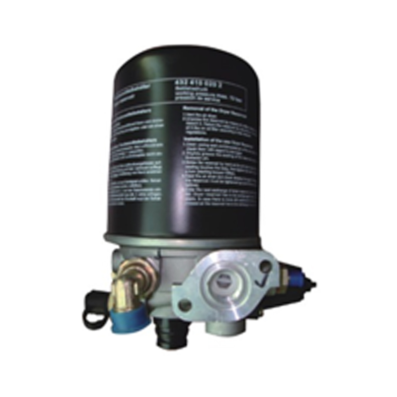
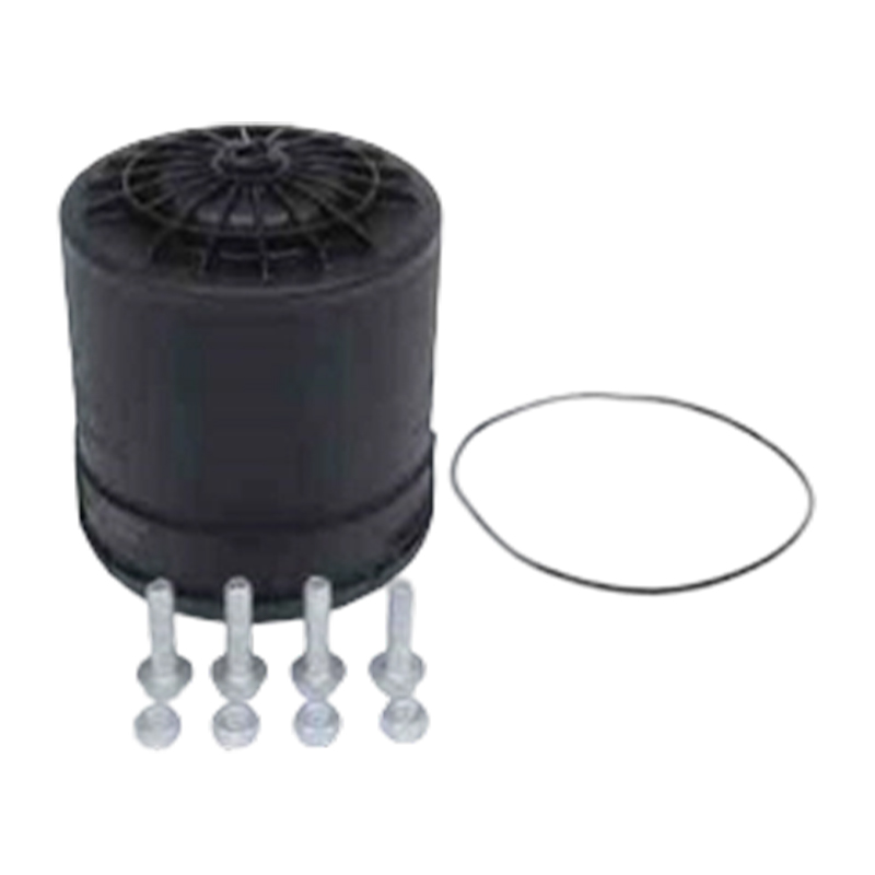 Custom Air Brake Dryer CartridgesCustomizable cartridges for commercial air brake systems help remove moisture and protect valves, chambers, and lines from corrosion and contaminants.View Product →
Replacing a cartridge on schedule is cheaper than replacing the valves downstream of it. A dryer that is losing pressure through the purge port, or that fails to purge at all, should be treated as a system fault rather than a nuisance. More on dryer assemblies and their service life is covered in our heavy-duty truck air dryer assemblies range.
Quick release valves
A quick release valve with a worn exhaust seat bleeds continuously once it has been actuated, and it usually passes the static test while failing the applied test. This is a classic "intermittent" leak that vanishes on the inspection bench.
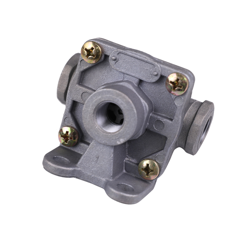 Standard Commercial Vehicle Quick Release ValveQuick-release valve for heavy-duty air brake systems rapidly discharges compressed air from brake chambers to improve response and reduce wear.View Product →
Foot brake valves and treadle assemblies
The treadle valve sits at the centre of the applied test, so a marginal inlet or exhaust seat there will fail a truck that otherwise looks fine. Look for a slow creep on the gauge while the pedal is held perfectly still, and check the exhaust port for a bubble that grows at a steady rate.
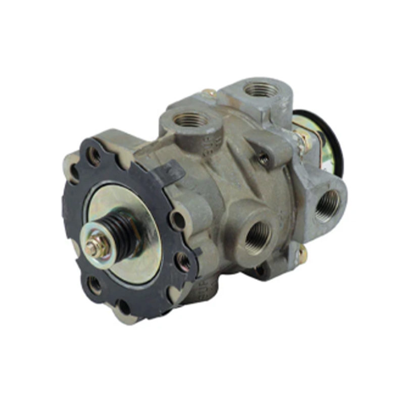 E-6 Professional Dual-Circuit Treadle Brake Valve F41050Dual-circuit foot brake valve with linear pressure response and redundant secondary circuit for precise, stable braking in commercial vehicles.View Product →
Relay valves and multi-circuit protection valves
Relay valves multiply the signal pressure at the axle, which means a small seat defect becomes a large air loss. Multi-circuit protection valves sit between the supply and every downstream circuit, so a leaking check valve inside one of them can make an entire vehicle look like it has a dozen small leaks at once. Our multi-circuit protection valves for trucks page sets out the port and opening-pressure options that matter when specifying a replacement.
Brake chambers and diaphragms
Chamber failures are usually obvious — a split service diaphragm loses air as soon as the pedal moves — but clamp band distortion and corroded housing joints produce slower, more confusing losses. Any chamber that has been in service through several winters is worth inspecting for corrosion pitting around the band before it is blamed for a pressure loss it did not cause.
Fittings, tubing and couplings
Push-to-connect fittings account for a large share of small, distributed losses. They are also the cheapest thing on the vehicle to fix, which is why a systematic soap test of every fitting takes priority over condemning valves. On combination vehicles, the gladhand seals deserve the same attention.
Why 3 psi and 4 psi are not arbitrary numbers
Technicians sometimes ask why a combination is allowed one more psi than a solo tractor. The answer is volume. A tractor-trailer combination carries a substantially larger air volume across more pipework, more fittings and an extra coupling interface. The allowable loss scales with the number of potential leak paths, so the standard gives the combination a marginally larger absolute allowance while requiring essentially the same relative tightness.
Take the allowance seriously in both directions. A combination that loses 3.9 psi has passed the letter of the rule but is on the edge, and an edge vehicle will fail within a few months as seals harden. Recording the actual number rather than a tick box turns a pass/fail inspection into a trend, and trends are what allow a workshop to replace a valve before it strands a truck.
Allowable pressure loss at the reference limits
Single, static 1 min2 psi
Combination, static 1 min3 psi
Single, applied 3 min3 psi
Combination, applied 3 min4 psi
Conditions that distort a leak-down reading
The gauge does not know why the pressure changed. Several physical effects can push a healthy system over the limit or hide a genuine leak, and a technician who ignores them will chase the wrong part.
Temperature
Compressed air cools after the compressor unloads, and cooling produces a pressure drop with no leak at all. This is why the standard requires the system to stabilise before timing starts. The opposite happens in a cold workshop: seals that are stiff at minus 10 °C may seal imperfectly until the vehicle has run for ten minutes. Test in the condition the vehicle actually operates in, or note the ambient temperature on the job card.
Moisture and freezing
Water carried through an exhausted desiccant bed can freeze inside a valve body overnight and produce a leak that disappears by mid-morning. A vehicle that only fails on cold mornings is telling you something about the dryer, not about the valve it is blaming.
Line pressure at the start of the test
Leak rate is proportional to pressure. A test started at 100 psi will always read lower than one started at 125 psi. Standardise the starting pressure across the fleet or the numbers stop being comparable.
Mechanical loading
Twisted chassis, a suspension at full bump, or a cab tilted forward can all change the geometry of a pipe run and open a joint that is tight when the vehicle sits level. Test on level ground with the vehicle in its normal ride position.
Instrument error
A dash gauge with a 10 psi sweep between graduations cannot resolve a 2 psi change. Use a dedicated test gauge, and check it against a known reference at least annually. An out-of-calibration gauge is a very expensive way to replace valves that were never faulty.
Tools that shorten diagnosis
Soap solution remains the workhorse, but two other tools earn their place in a busy workshop.
- Ultrasonic leak detector. Converts turbulent air escaping a small orifice into an audible signal, which makes it possible to locate leaks inside a loom of pipes without dismantling anything. Best for losses under 5 psi per minute where bubbles are too slow to see.
- Inline flow meter. Measures actual air consumption at the compressor discharge and gives a single figure for the whole vehicle. Useful for fleet benchmarking because it is fast and does not require full stabilisation.
- Pressure decay logger. A digital gauge that records pressure against time produces a curve rather than a single number. A curve with a sharp knee usually indicates a valve cracking open at a specific pressure; a straight line usually indicates a distributed set of small leaks.
None of these replace the timed test. They shorten the interval between "this vehicle fails" and "this component is why".
Building the test into a preventive maintenance schedule
A leak-down test performed once a year catches faults; performed quarterly it prevents them. The intervals below reflect typical heavy-haul and regional distribution duty cycles, and should be shortened for vehicles running in high-corrosion environments or on constant stop-start work.
| Interval | Activity | Focus |
|---|---|---|
| Daily walkaround | Visual check, listen for audible leaks | Gladhand seals, chamber bands, obvious damage |
| Monthly | Static and applied leak-down test | Record actual psi loss, not pass/fail |
| Quarterly | Full soap test of all fittings and valve exhausts | Push-to-connect fittings, relay valve exhausts |
| Annually | Dryer cartridge replacement, purge valve inspection | Desiccant condition, purge seat, downstream corrosion |
| At any failure | Circuit isolation before parts replacement | Split tractor and trailer, then split by circuit |
The single most valuable habit is writing the measured number on the job card. A fleet that records 1.2 psi in March and 2.8 psi in September has a replacement decision to make; a fleet that records only "pass" has nothing.
Mistakes that make a good test meaningless
- Testing with the parking brake applied. The spring chambers are held in the applied position, so the park circuit is not being evaluated the way the standard intends.
- Starting the timer before the system has stabilised. The first 30 seconds after shutdown are dominated by cooling, not by leakage.
- Using the dashboard gauge as the reference instrument. It is a driver aid, not a measurement device.
- Testing at whatever pressure the truck happens to be at. Standardise the starting pressure or the numbers cannot be compared across vehicles or across months.
- Replacing the most expensive valve first. Isolate by circuit, then by fitting, then by component.
- Skipping the trailer split. A combination that fails by 1 psi is almost always a trailer-side or coupling-side issue, and the split costs four minutes.
- Ignoring auxiliary circuits. Gearbox valves, levelling valves and cab suspension all draw from the same supply and can mimic brake faults convincingly.
Questions that come up on the workshop floor
Can I do a leak-down test on my own?
Yes. Chock the wheels, charge the system to cut-out, shut the engine down and run both the static and applied tests with a stopwatch. A second person helps when you are watching the gauge and spraying soap solution at the same time, but it is not essential.
How long should the whole test take?
Roughly 12 to 15 minutes including stabilisation, and about 20 minutes if you split the tractor and trailer and soap-test every fitting. Budget longer on a vehicle that has not been tested in a year.
My truck passes the static test but fails the applied test. What does that mean?
It normally means the leak is downstream of the foot valve and only opens when pressure is commanded: a service chamber diaphragm, a relay valve, a quick release valve or a modulator. Work from the pedal outward and test each axle circuit separately if the vehicle has isolation valves.
Is a 2 psi loss in one minute acceptable on a combination?
Yes, that is comfortably inside the 3 psi allowance. The number worth watching is the trend. A combination that reads 2.8 psi should be scheduled for investigation before it becomes a roadside failure.
Does the engine need to be running during the test?
No. The test is performed with the engine off and the ignition on, so the gauges and warning systems remain live. A running engine keeps the compressor cycling and makes the gauge unreadable.
How do European and American tolerances compare in practice?
They are closer than the units suggest. Both systems are asking for a pressure loss small enough that the compressor can keep up without excessive cycling and small enough that the spring brakes will hold for a reasonable parking period. If you service a mixed fleet, keep both reference tables on the workshop wall and always defer to the vehicle's own specification.
What if the vehicle passes but the driver still reports slow pressure build-up?
Leak-down and build-up are different faults. A slow build-up points at the compressor, the governor setting, the dryer restriction or a blocked discharge line. Test the leak rate first, then investigate charge time separately.
Run the test in the order described, write the actual number down, and treat every pass as data rather than a green tick. A truck that loses 1 psi today and 2.5 psi in six months has not failed yet — but it has told you exactly which circuit to inspect on the next service, and that is the point of the exercise.
Our Main Products
Copyright © Zhejiang Gongzheng Machinery Co., Ltd. All Rights Reserved.
