


 Français
 Español
 中文简体
 русский

Gongzheng
Gongzheng
Gongzheng
Gongzheng
Gongzheng
Gongzheng
Gongzheng
Gongzheng
Gongzheng
Gongzheng
Gongzheng
Gongzheng
Gongzheng
Gongzheng
Gongzheng
Gongzheng
Industry News
How Does a Spring Brake Chamber Work? Air Pressure, Spring Force and Safety

Content
- 1 How a Spring Brake Chamber Works: The Short Answer
- 2 The Two Chambers Inside One Housing
- 3 Step by Step: From Foot Pedal to Parking Brake
- 4 Why Pressure Loss Sets the Spring Instead of Releasing It
- 5 How the Air Path and Valves Coordinate
- 6 Key Specifications Buyers Compare
- 7 Long-Stroke and Standard-Stroke Chambers
- 8 Installation and Setup Factors That Change Performance
- 9 Failure Symptoms and Diagnostic Logic
- 10 Service, Maintenance, and Replacement Decisions
- 11 Materials, Environment, and Duty Cycle
- 12 Specification Checklist for Fleet and Product Teams
- 13 Frequently Asked Questions
- 13.1 Does a spring brake chamber use air pressure to apply the parking brake?
- 13.2 Why does a truck lose its parking brake release after sitting for a few days?
- 13.3 Can a spring brake chamber be repaired in the field?
- 13.4 What happens if the service diaphragm fails?
- 13.5 How do I know whether I need a standard-stroke or long-stroke chamber?
- 13.6 Why does the chamber release slowly after the parking brake is turned off?
- 13.7 Does moisture in the air system affect spring brake chamber life?
- 13.8 What should be checked after installing a new spring brake chamber?
How a Spring Brake Chamber Works: The Short Answer
A spring brake chamber works by combining two pneumatic functions in one compact housing: a service brake chamber that applies braking force when air pressure enters, and a spring brake chamber that stores mechanical energy in a heavy coil spring. Under normal driving conditions, compressed air holds that spring compressed and keeps the parking brake released. When air pressure drops, or when the driver operates the parking control, the spring extends and applies the brake through the same pushrod and slack adjuster assembly.
The important point is that the spring does not release the brake. It applies the brake. Air pressure releases the spring. That inversion is the basis of the fail-safe design used on heavy trucks, tractors, trailers, and buses. If a supply line ruptures, a diaphragm fails, or the vehicle loses air pressure, the chamber defaults toward braking rather than rolling freely.
Service side Air pressure pushes a diaphragm and pushrod to apply normal foot-brake force.
Spring side A compressed coil spring stores parking and emergency brake energy.
Fail-safe logic Low pressure lets the spring extend, so the brake applies automatically.
The Two Chambers Inside One Housing
A combined spring brake chamber is not a single air chamber with one diaphragm. It is a stacked assembly with two working sections separated by a strong pressure plate and a sealed spring cavity. The service section behaves like a standard air brake chamber. The spring section behaves like a mechanical actuator with a pneumatic release. Understanding the boundary between those sections explains most installation, troubleshooting, and replacement decisions.
Service chamber: the normal braking function
When the driver presses the brake pedal, the foot brake valve delivers modulated air pressure to the service port. That pressure acts on the service diaphragm, which pushes a plate and pushrod outward. The pushrod movement rotates the slack adjuster, which turns the brake camshaft or applies the air disc brake caliper. When the pedal is released, the service pressure exhausts and a return spring moves the diaphragm and pushrod back to the released position.
This section is proportional. More pedal pressure produces more air pressure, more pushrod stroke, and more braking force, up to the vehicle’s designed limit. The service chamber therefore does the everyday work of slowing and stopping the vehicle.
Spring chamber: the parking and emergency function
The spring section contains a large compression spring. In the released condition, air pressure enters the spring chamber and pushes against a piston or diaphragm plate, compressing the spring. The spring remains held back as long as hold-off pressure is present. When the parking valve exhausts that pressure, the spring extends and pushes the same pushrod assembly outward. The brake applies mechanically, without relying on the service diaphragm.
This is why a parked vehicle with a charged air system remains released, while a vehicle that loses air pressure gradually applies its spring brakes. The spring is the energy source; compressed air is the release mechanism.
| Feature | Service chamber | Spring chamber | Combined chamber |
|---|---|---|---|
| Primary energy | Compressed air from foot valve | Mechanical coil spring | Air release plus stored spring force |
| Normal driving state | Released when pedal is up | Held compressed by air pressure | Spring released by hold-off air |
| Application method | Proportional foot-brake pressure | Parking valve exhaust or pressure loss | Service braking and parking braking |
| Failure behavior | May lose service braking force | Spring applies brake automatically | Fails toward a safer braking state |
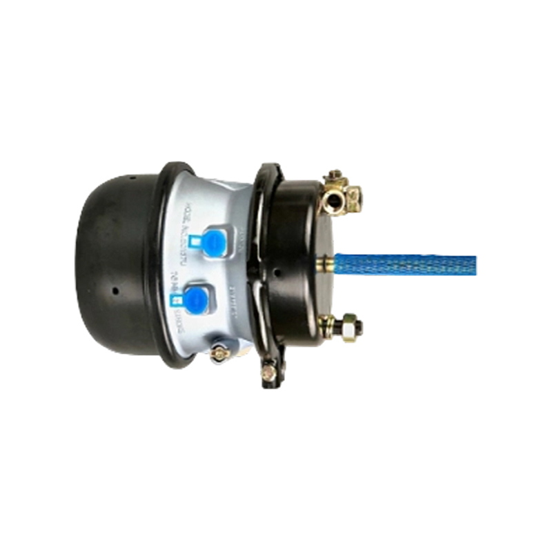 Advanced Dual-Function Spring Brake Chamber T33226Dual-diaphragm T33226 combines service and spring-loaded parking/emergency braking, making it relevant for tracing release, service, parking, and emergency pressure paths.View Product →
Step by Step: From Foot Pedal to Parking Brake
The working sequence is easier to follow when separated into release, service application, parking application, and emergency application. Each stage uses a different pressure path, but all stages act through the same pushrod and foundation brake hardware.
- Air system charge: The compressor builds pressure, the air dryer removes moisture, and the protection valve distributes air to circuits. Hold-off pressure reaches the spring chamber.
- Parking release: The parking control valve admits air into the spring cavity. The spring compresses, the pushrod retracts, and the parking brake releases.
- Service braking: The foot brake valve sends modulated pressure to the service port. The service diaphragm moves the pushrod to apply the foundation brake.
- Service release: Pressure exhausts through the foot valve or relay valve. The service return spring retracts the pushrod.
- Parking application: The parking valve exhausts spring-chamber pressure. The spring extends and applies the brake mechanically.
- Emergency application: If supply pressure falls below the release threshold, the spring extends without driver input, bringing the vehicle to a controlled stop.
Conceptual pressure response of a spring brake chamber
0 bar
Spring applied
2 bar
Partial release
4.5 bar
Release threshold zone
6 bar
Fully released, service available
8 bar
Service pressure range
The chart is conceptual. Release pressure, hold-off pressure, and maximum service pressure must be checked against the chamber data sheet and the vehicle air system specification.
Why Pressure Loss Sets the Spring Instead of Releasing It
The fail-safe behavior comes from the spring’s stored energy. While the vehicle is running, the spring is held in a compressed state by air pressure. That air pressure is not the braking force. It is the release force. When the release force disappears, the spring expands and applies the brake. The system therefore fails in the direction of braking rather than free rolling.
This design has practical consequences for drivers and maintenance teams. A vehicle that has been parked for a long period may slowly lose air pressure and apply its spring brakes. A tractor protection valve may close to protect the tractor if trailer pressure drops. A broken spring brake hose can cause a parking brake application or a dragging brake, depending on how the chamber and valve circuit are arranged. Technicians should never assume that a released parking brake means the spring cavity is safe to open.
Never open the spring cavity The spring stores enough energy to cause serious injury. Replacement, not field disassembly, is the normal service approach.
Secure the vehicle first Use wheel chocks and follow lockout procedures before working on air lines or chamber mounting hardware.
Respect the release threshold Pressure below the release threshold can apply the brake even if the parking valve looks released.
How the Air Path and Valves Coordinate
A spring brake chamber does not work alone. Its behavior depends on the pressure path around it: supply, control, release, and protection. The compressor and air dryer condition the air. The circuit protection valve isolates circuits. The foot brake valve modulates service pressure. The relay valve shortens response time by supplying air closer to the chamber. The parking control valve controls spring-chamber pressure. Quick release valves speed exhaust in some circuits. ABS or EBS modulators adjust pressure during wheel-slip events.
Supply stage
The air dryer removes moisture and oil aerosol before air reaches the wet tank and protection valve. Clean, dry air protects diaphragms, seals, and valve seats.
Control stage
The foot valve or EBS foot module sends a pressure signal. Relay valves amplify or repeat that signal for faster chamber response.
Spring release stage
The parking valve charges the spring cavity to release the brake. Exhausting that cavity applies the parking brake.
Protection stage
Circuit protection and tractor protection valves preserve priority pressure and limit the effect of a single circuit failure.
Response time matters here. A chamber that receives pressure quickly but exhausts slowly can release unevenly, cause brake drag, or create timing differences between axles. A relay valve with adequate flow capacity and a clean exhaust path often has more influence on pedal feel and release timing than the chamber alone. When a vehicle has a slow release complaint, test the whole air path rather than replacing the chamber immediately.
Key Specifications Buyers Compare
Spring brake chambers may look similar from the outside, but the specification details determine fit, stroke, force, and service life. The chamber size is not the only number that matters. Stroke type, mounting bracket, port thread, pushrod length, clevis type, return spring force, diaphragm material, and corrosion protection all affect whether the part performs correctly in a given application.
| Specification | Typical meaning | Why it matters |
|---|---|---|
| Chamber size | T16, T20, T24, T30 and similar size classes | Affects available force and foundation brake balance |
| Stroke type | Standard stroke or long stroke | Changes usable pushrod travel and adjustment range |
| Pushrod length | Distance from chamber face to clevis pin | Must match bracket and slack adjuster geometry |
| Port thread | Metric, NPT, Voss, or platform-specific interface | Prevents leaks and installation mismatch |
| Return spring | Service-side return force | Controls release speed and residual drag |
| Sealing material | Rubber compound, reinforced diaphragm, O-ring seals | Resists heat, oil, water, and ozone aging |
| Surface protection | Coating or plating on housing and hardware | Improves salt-spray and corrosion resistance |
For replacement planning, do not rely only on the vehicle model. Match the chamber by port interface, stroke, pushrod projection, bracket orientation, and approved operating pressure. Small dimensional errors can cause excessive slack adjuster travel, poor release, or interference with suspension and frame components. A verified catalogue such as spring brake chambers for heavy-duty trucks helps narrow the specification before ordering.
Long-Stroke and Standard-Stroke Chambers
Long-stroke spring brake chambers provide more pushrod travel than standard-stroke designs. They are not simply longer versions of the same part. The internal geometry, return spring, diaphragm plate, and mounting envelope may differ. The foundation brake and slack adjuster must be compatible with the available stroke, and the brake adjustment procedure must respect the correct applied stroke limit.
| Consideration | Standard stroke | Long stroke |
|---|---|---|
| Pushrod travel | Shorter usable travel | Extended usable travel |
| Typical role | Many conventional foundation brake layouts | Layouts requiring greater adjustment range |
| Installation clearance | More compact envelope | Needs adequate pushrod and bracket clearance |
| Adjustment check | Use the specified applied stroke mark | Must use the long-stroke limit, not a standard-stroke value |
| Risk if mismatched | Stroke may be too short for the layout | Over-stroke or interference may occur if the bracket is wrong |
When long-stroke chambers are installed, verify the pushrod length at the clevis pin rather than judging by the chamber can. A chamber may fit the bracket and still have the wrong pushrod projection. The release position should leave the correct free play, and the fully applied position should stay within the vehicle manufacturer’s stroke limit. Replacing a standard-stroke chamber with a long-stroke unit without confirming the foundation brake design is a common source of adjustment and drag complaints.
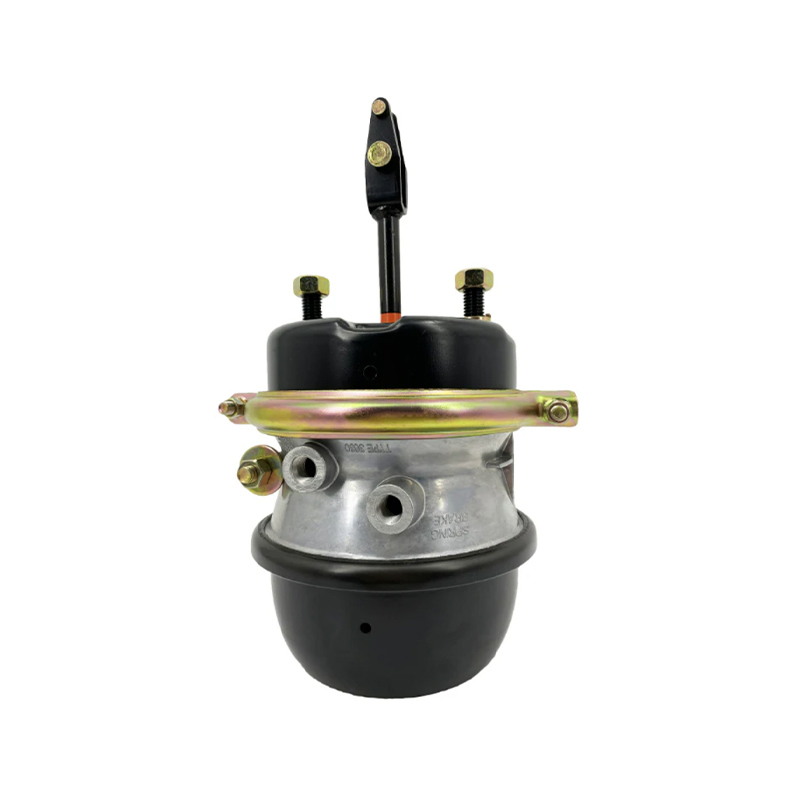 T34322 All-Weather Sealed Combination Brake ChamberSealed T34322 T30/30 combination chamber suits cold, wet heavy-duty service; verify pushrod length and stroke limits during installation.View Product →
Installation and Setup Factors That Change Performance
Most spring brake chamber problems are not caused by the chamber alone. Installation geometry, air line routing, moisture control, and adjustment settings determine whether the part performs as designed. A chamber that is mechanically correct but installed with a misaligned bracket, a kinked hose, or an incorrect clevis angle may still produce drag, slow release, or uneven braking.
Bracket alignment
The chamber should sit square to the pushrod path. Side loading wears the bearing surface and can bend the pushrod.
Pushrod free play
Check free travel at the clevis or slack adjuster. Too little free play can cause drag; too much can increase stroke.
Port and hose routing
Use the correct thread and seal. Route hoses away from heat, sharp edges, and suspension travel paths.
Moisture protection
Water and oil in the air supply accelerate diaphragm and seal degradation. Service the air dryer and drain tanks.
Clamp band condition
The clamp band must be seated correctly. A cocked band can leak or release under pressure.
System pressure test
After installation, check for leaks at both service and spring ports, then confirm parking release and application.
On trailers, the spring brake chamber interacts with the trailer control valve, emergency relay valve, and parking release functions. A trailer that releases slowly may have a restricted line, a failing quick release valve, or a chamber with the wrong spring cavity volume. On tractors, the parking control and tractor protection valve can affect how quickly the spring brakes apply when the trailer is disconnected. Always test the complete circuit, not only the chamber.
Failure Symptoms and Diagnostic Logic
Symptoms should be separated into service-brake complaints, parking-brake complaints, and air-loss complaints. That separation prevents unnecessary replacement. A dragging brake may be a chamber issue, but it may also be a collapsed hose, a stuck relay valve, a misadjusted slack adjuster, or a parking valve that does not fully exhaust.
| Symptom | Likely cause | First check |
|---|---|---|
| Parking brake will not release | Low hold-off pressure, blocked line, faulty parking valve | Measure pressure at the spring port and check valve exhaust |
| Brake drag after release | Slow exhaust, return spring issue, misadjusted pushrod | Check release time, free play, and hose restrictions |
| Air leak at chamber | Diaphragm, seal, clamp band, or port fitting leak | Leak-test service and spring sections separately |
| Weak service braking | Low service pressure, diaphragm damage, excessive stroke | Compare applied stroke and pressure with specification |
| Spring brake applies too early | Pressure loss, restricted supply, faulty protection valve | Check system pressure and circuit isolation behavior |
| Noise or vibration during release | Loose mounting, worn clevis, air path pulsation | Inspect bracket, fasteners, and hose routing |
A practical diagnostic order is pressure, leakage, stroke, and mechanical condition. Confirm that the chamber receives the correct pressure before condemning it. Then check for leakage at the service port, spring port, clamp band, and exhaust path. Measure pushrod stroke against the correct standard-stroke or long-stroke limit. Finally, inspect the mounting bracket and clevis for wear. This sequence avoids replacing a good chamber when the real fault is a valve or a blocked line.
Service, Maintenance, and Replacement Decisions
Spring brake chambers are generally treated as replacement assemblies rather than field-rebuildable spring units. The spring cavity stores high energy, and the clamp band and pressure plate must be handled with controlled procedures. Routine service therefore focuses on inspection, air quality, leak testing, stroke measurement, and replacement when the chamber no longer meets specification.
Inspect the chamber during scheduled brake service. Look for cracked or swollen diaphragms, corrosion around the clamp band, oil contamination in the air system, damaged pushrods, and loose mounting hardware. Check the parking release and application response. On vehicles with frequent stop-start duty, the spring chamber may cycle many times per day, so release time and hold-off pressure deserve attention.
Replace when stroke is out of range If correct adjustment cannot bring applied stroke within the limit, the chamber or foundation brake needs attention.
Replace when leakage is internal A chamber that leaks between sections or past a seal cannot be corrected by external adjustment.
Replace when corrosion is advanced Heavy corrosion at the clamp band or ports can compromise sealing and structural integrity.
For a step-by-step field reference, see this guide to servicing a spring brake chamber. It explains the practical checks that should happen before replacement, including pressure verification and safe handling. Maintenance teams should also record chamber age, vehicle duty cycle, and repeated fault patterns so that replacement intervals reflect actual operating conditions rather than a single generic number.
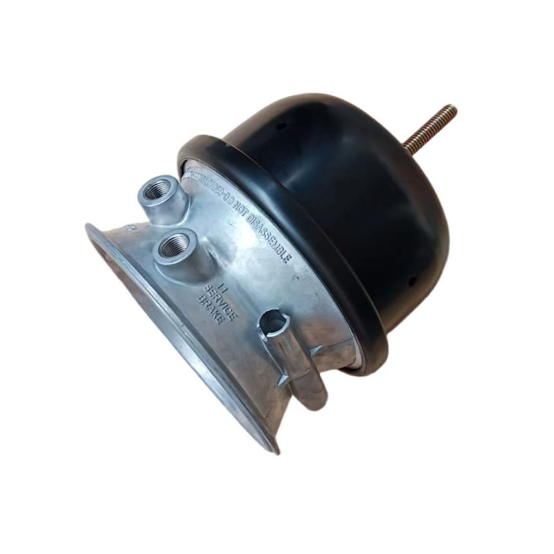 3030 Brake Chamber Piggyback Kit for Emergency Brake MaintenancePiggyback kit restores the spring-actuated section with a high-tension spring, diaphragm, and seals, supporting cost-effective refurbishment in demanding operating conditions.View Product →
Materials, Environment, and Duty Cycle
The operating environment changes how a spring brake chamber ages. Salt spray attacks the housing and clamp band. Heat accelerates rubber aging. Ozone and sunlight crack unprotected elastomers. Oil carryover from the compressor can soften diaphragms and swell seals. Condensation inside the air system can freeze in cold weather and block small passages. A chamber that performs well in a dry, mild climate may need a different protection level in a coastal fleet or a winter road-maintenance operation.
Corrosion exposure
Coated housings, plated hardware, and sealed interfaces help resist road salt and humidity. Inspect clamp bands and port threads at every brake service.
Thermal cycling
Repeated heating and cooling can stiffen rubber parts and change release behavior. Brake drag increases heat, so correct adjustment supports seal life.
Contaminated air
Oil and water shorten diaphragm life. Air dryer maintenance is part of brake chamber reliability, not a separate concern.
Duty cycle
Urban delivery, refuse, and coach applications may cycle parking brakes far more often than long-haul tractors. Match inspection frequency to use.
For product teams and fleet engineers, the useful question is not simply “which chamber fits?” It is “which chamber construction matches the duty cycle and environment?” A sealed combination chamber with enhanced corrosion protection may be the better choice for winter-service trailers, while a standard service chamber may be sufficient for a protected on-highway application. The specification should connect to the real operating profile.
Specification Checklist for Fleet and Product Teams
Before approving a spring brake chamber for a vehicle platform or replacement programme, confirm the following points. The checklist is intentionally practical: each item prevents a specific installation or performance problem.
Confirm service and spring port threads against the harness and valve interfaces.
Verify standard-stroke or long-stroke configuration against the foundation brake.
Measure pushrod projection at the clevis pin, not only the chamber body length.
Check bracket orientation and clearance through full suspension travel.
Confirm hold-off pressure and release behavior at the specified test pressure.
Review diaphragm and seal material for oil, heat, and low-temperature exposure.
Check clamp band, port protection, and surface coating for the target market.
Validate the parking release and emergency application sequence after installation.
Gongzheng’s commercial vehicle braking range includes spring brake chambers, service chambers, relay valves, protection valves, air dryers, and related pneumatic components. The engineering logic across those parts is connected: clean air, stable pressure, fast response, and correct release behavior all support the chamber’s function. A chamber specification that ignores the surrounding air path may fit mechanically but still deliver poor release timing or short service life.
Frequently Asked Questions
Does a spring brake chamber use air pressure to apply the parking brake?
No. Air pressure releases the parking brake by holding the spring compressed. When the parking valve exhausts air, or when supply pressure falls, the spring extends and applies the brake. The service section uses air pressure to apply normal foot braking, but the spring section uses stored mechanical force for parking and emergency braking.
Why does a truck lose its parking brake release after sitting for a few days?
Air pressure can slowly leak from the system, the parking valve, or a connected circuit. Once spring-chamber pressure drops below the release threshold, the spring begins to apply. This may be normal after long storage, but a rapid or repeated loss suggests a leak that should be traced at the parking valve, hoses, fittings, or chamber seals.
Can a spring brake chamber be repaired in the field?
The spring cavity is dangerous and should not be opened without controlled procedures and the correct equipment. In most service operations, the chamber is replaced as an assembly. External items such as hoses, fittings, clevis pins, and mounting hardware can be serviced separately. If the diaphragm or internal seal has failed, replacement is the normal path.
What happens if the service diaphragm fails?
A failed service diaphragm usually causes weak or no service braking on that chamber, and it may produce an air leak at the chamber or exhaust. The spring section may still hold off and release normally, but the vehicle should not continue in service until the fault is corrected. A service diaphragm failure is different from a spring cavity failure, so leak-test both sections separately.
How do I know whether I need a standard-stroke or long-stroke chamber?
Use the foundation brake and vehicle specification, not guesswork. Check the approved applied stroke limit, pushrod projection, bracket clearance, and slack adjuster geometry. A long-stroke chamber installed where a standard-stroke unit belongs can create over-stroke or interference problems, while a standard-stroke chamber in a long-stroke layout may run out of adjustment range.
Why does the chamber release slowly after the parking brake is turned off?
Slow release can come from a restricted supply line, a parking valve that does not exhaust quickly, a blocked exhaust port, a kinked hose, or a chamber with abnormal internal restriction. Compare release time with a known-good chamber on the same vehicle. If the delay follows the valve or line, replace the chamber only after confirming the air path.
Does moisture in the air system affect spring brake chamber life?
Yes. Water promotes corrosion and can freeze in cold weather. Oil carryover can soften rubber parts. Both conditions shorten diaphragm and seal life. Air dryer maintenance, tank draining, and correct filtration are part of keeping the chamber reliable. A chamber replacement without correcting contaminated air may fail again in a short period.
What should be checked after installing a new spring brake chamber?
Check for leaks at the service port, spring port, clamp band, and fittings. Confirm parking release and application. Measure pushrod stroke and free play. Verify that hoses do not rub or stretch through suspension travel. Then perform a road or controlled test to confirm balanced braking and release behavior before the vehicle returns to service.
Our Main Products
Copyright © Zhejiang Gongzheng Machinery Co., Ltd. All Rights Reserved.
