


 Français
 Español
 中文简体
 русский

Gongzheng
Gongzheng
Gongzheng
Gongzheng
Gongzheng
Gongzheng
Gongzheng
Gongzheng
Gongzheng
Gongzheng
Gongzheng
Gongzheng
Gongzheng
Gongzheng
Gongzheng
Gongzheng

Content
- 1 Begin With the Pressure Balance, Not the Pedal
- 2 Compressed Air Generation and Governor Control
- 3 Air Dryer Performance Changes Everything Downstream
- 4 Reservoirs, Four-Circuit Protection, and Pressure Priority
- 5 Foot Brake Valve: Graduated Control and Dual-Circuit Safety
- 6 Relay Valves and Quick Release Valves Shape Timing
- 7 Brake Chambers and Spring Brakes: Where Pressure Becomes Force
- 8 ABS, EBS, and Pressure Modulation
- 9 Parking, Emergency Release, and Trailer Circuits
- 10 Troubleshooting Matrix for Common Air Brake Complaints
- 11 Pressure Tests That Reveal the Difference Between “Works” and “Works Safely”
- 12 Maintenance Intervals and the Parts Most Often Replaced Too Late
- 13 Replacement Selection: Tolerances, Threads, and Real Operating Conditions
- 14 FAQ: How a Truck Air Brake System Works in Service
- 14.1 Why does a truck use air instead of hydraulic fluid?
- 14.2 What happens when one brake circuit fails?
- 14.3 Why do brakes release slowly after the pedal is released?
- 14.4 How does a spring brake chamber work?
- 14.5 Can an air dryer fault affect brake response?
- 14.6 What should be checked after replacing an air brake valve?
Begin With the Pressure Balance, Not the Pedal
The quickest way to understand a truck air brake system is to follow pressure balance. The pedal does not pull a cable or push fluid in the same way a light-duty hydraulic brake does. It opens and closes air passages. Compressed air then acts on a piston or diaphragm, and that movement becomes brake force at the wheel. If pressure is slow to build, slow to exhaust, trapped in the wrong circuit, or contaminated with moisture, the pedal feel may still seem normal while stopping performance changes.
That is why a useful diagnostic sequence starts with the air source, then the control valve, then the relay and release path, and finally the chamber and foundation brake. Replacing a chamber before checking relay valve response can hide a pressure-delivery problem. Replacing a foot valve before checking the dryer and reservoir condition can put a new valve into the same wet, oily air stream that damaged the old one.
Field rule: an air brake fault is a pressure fault until proven otherwise. Check build-up, leakage, exhaust speed, circuit isolation, and chamber stroke before assuming the pedal assembly is the cause.
Supply Side
Compressor, governor or unloader, air dryer, reservoirs, drain valves, and circuit protection. This side decides whether the system has dry, stable pressure available.
Control Side
Foot brake valve, hand control valve, relay valves, quick release valves, load sensing, and trailer control. This side decides how quickly and proportionally pressure arrives.
Apply Side
Service chambers, spring brake chambers, slack adjusters, foundation brakes, and ABS or EBS modulators. This side turns pressure into stopping force.
Release Side
Exhaust ports, quick release valves, relay valve exhaust, and parking release circuits. This side decides whether brakes release cleanly or drag.
Compressed Air Generation and Governor Control
A truck air brake system begins at the compressor. The compressor draws in air, pressurizes it, and sends it toward the air dryer and reservoirs. The governor or unloader valve watches reservoir pressure and controls whether the compressor keeps charging or runs unloaded. Typical commercial vehicle systems cut out somewhere around 8.3 to 8.6 bar, or roughly 120 to 125 psi, and cut back in near 100 psi, but the exact figures must follow the vehicle specification. The important point is not a single number; it is repeatable cut-in and cut-out behavior.
If cut-out pressure is too low, the system may feel weak after one or two pedal applications. If cut-in pressure is too high, the compressor may run hot or load the engine unnecessarily. If the governor signal line is blocked or leaking, the compressor may stay loaded, causing excessive moisture and heat, or it may fail to charge at all. A gauge that rises quickly but falls sharply after shutdown often points to a check valve, drain valve, or reservoir leak rather than the compressor alone.
Technicians should watch build-up time from cut-in to cut-out, unloaded running behavior, and whether the compressor restarts promptly after a small pressure drop. A slow build-up with a healthy compressor can come from a restricted intake, a tired compressor, a leaking discharge line, or a dryer purge valve that does not seat. The governor is a small part with a large effect on moisture control, fuel use, and brake response.
Air Dryer Performance Changes Everything Downstream
The air dryer removes water vapor and oil carryover before air enters the wet tank. It also contains a purge valve and often a heater, pressure protection valve, or integrated air processing unit, depending on the platform. Moisture that passes the dryer does not disappear. It condenses in reservoirs, valves, and chambers. In cold weather it can freeze at an exhaust port or inside a signal line. In warm weather it supports corrosion and seal swelling. Either way, the brake system loses repeatability.
A dryer that purges frequently, releases oil mist, or leaves water in the wet tank is not doing its job. A dryer cartridge that is overdue can raise dew point and allow emulsion to travel farther into the system. A purge valve that leaks can cause the compressor to cycle too often. A heater circuit fault can cause ice formation at the purge port in winter. Service decisions should be based on cartridge life, reservoir moisture, purge behavior, and the vehicle duty cycle, not only on a visual inspection of the housing.
For fleets that replace complete dryer assemblies, the matching points are port threads, mounting bracket geometry, heater voltage, purge reservoir volume, and whether the unit includes an integrated multi-circuit protection valve. A compact unit can look correct on the outside and still have the wrong internal bypass or safety valve setting. That is why the assembly part number and pressure specification matter as much as the hose layout.
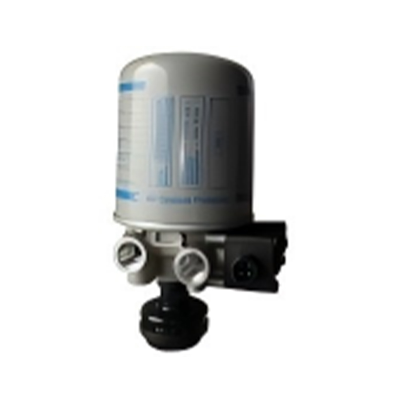
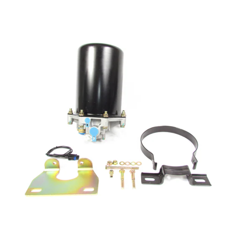 Heavy-Duty AD-9 Air Dryer Assembly with Mounting BracketFor complete dryer replacement, this A34108-series assembly includes an integrated bracket, desiccant cartridge, purge valve, and heater.View Product →
When specifying replacement air treatment, review heavy-duty truck air dryer assemblies against the original circuit layout, including drain access and heater connector position. A dryer that is difficult to service often gets neglected, and neglected air treatment is one of the most common reasons a new valve develops a sticky or leaking fault.
Reservoirs, Four-Circuit Protection, and Pressure Priority
Compressed air is stored in reservoirs so the brake system can respond before the compressor catches up. The wet tank receives air first, then the dryer or processing unit feeds the primary and secondary circuits. A four-circuit protection valve divides pressure among service brake circuits and auxiliary circuits. If one circuit loses pressure, the protection valve should preserve enough pressure in the remaining circuits to allow a controlled stop. This is the practical reason a truck can still brake with one circuit failed, although performance and pedal travel will change.
Pressure limiting and safety valves protect components from overpressure. Drain valves remove condensate. Check valves prevent backflow when pressure drops or when a trailer is disconnected. A missing or stuck check valve can make two circuits interact in ways that are hard to diagnose from the driver's seat. For example, a leaking primary circuit may drain pressure from the secondary circuit through a failed separation point, causing both gauges to fall together.
During inspection, verify that each circuit holds pressure independently, that the protection valve opens and closes at the correct setting, and that drains are not blocked. A reservoir that drains clear water but refills with milky emulsion within a day is telling you the dryer, compressor, or oil carryover problem is still active. Do not treat the drain as the repair.
Foot Brake Valve: Graduated Control and Dual-Circuit Safety
The foot brake valve is the driver's pressure command. In a dual-circuit valve, pedal movement operates two separate pressure sections. Light pedal application should produce a low, proportional pressure signal. As the pedal moves farther, pressure rises smoothly. When the pedal is released, the valve should exhaust quickly so the brakes release without drag. A foot valve that is sticky, noisy, slow to exhaust, or uneven between circuits changes the entire feel of the system, even if the chambers are healthy.
Pedal free play and pushrod adjustment matter. Too much free play can reduce usable travel. Too little can preload the valve and cause dragging or residual pressure. The return spring, treadle pivot, roller, and plunger must move freely. Contamination at the inlet seat can cause a slow leak or a pressure rise after release. A worn exhaust seat can cause air to escape at the treadle area. These faults are often intermittent because they depend on temperature, vibration, and how long the pedal is held.
For replacement, the critical details are circuit arrangement, port thread type, pedal angle, mounting pattern, and whether the valve includes an electronic sensing element or a switch. A valve that fits the mounting bracket but has the wrong pedal ratio can feel abrupt or fail to reach full application pressure. A valve with the wrong exhaust characteristic can make release sluggish, especially on long wheelbase vehicles.
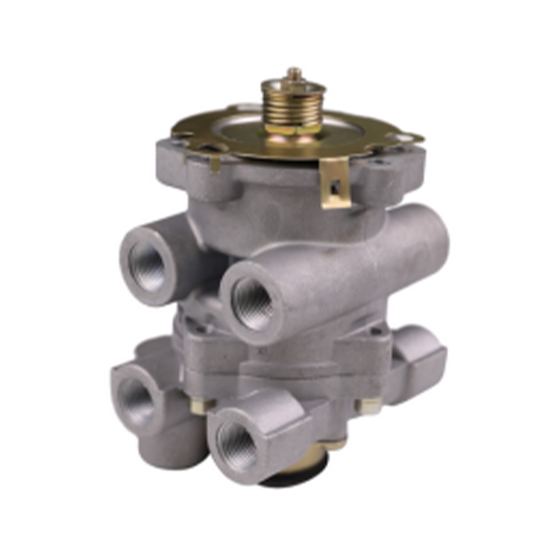 E-8P Dual-Circuit Foot Brake Valve F41040Dual-circuit foot brake valve with linear pressure response and redundant secondary circuit, intended for commercial vehicle service braking systems.View Product →
Relay Valves and Quick Release Valves Shape Timing
A relay valve shortens the distance the control signal must travel. The foot valve sends a small pilot signal to the relay valve, and the relay valve opens a larger reservoir passage close to the brake chambers. This reduces lag and gives more stable pressure delivery on long vehicles. The relay valve also exhausts downstream pressure when the signal drops. If the relay valve is slow, cracked, or contaminated, the pedal may feel normal while the brakes apply late or release late.
A quick release valve speeds exhaust from the chamber side of the circuit. It is especially useful where the chamber is far from the foot valve or relay valve. A quick release valve that leaks, sticks, or has a blocked exhaust can cause dragging brakes, hot drums, and poor fuel economy. It can also make a truck pull to one side if the release timing differs across the axle.
Conceptual timing profile: the goal is not simply maximum pressure, but predictable pressure rise and a clean drop toward zero when the pedal is released.
When diagnosing a timing complaint, compare left and right chambers with a pressure gauge or diagnostic readout. Check relay valve exhaust for blockage, inspect signal lines for kinks, and confirm that the quick release valve is installed in the correct flow direction. A quick release valve installed backward can produce a false repair: the pedal may feel firmer, but release and modulation become worse.
Brake Chambers and Spring Brakes: Where Pressure Becomes Force
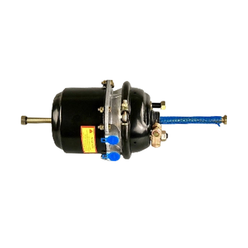
A service brake chamber converts air pressure into pushrod travel. Inside, a diaphragm separates the pressure side from the spring side. As pressure rises, the diaphragm moves a plate and pushrod, which operates the slack adjuster and foundation brake. A spring brake chamber adds a large storage spring for parking and emergency braking. Air pressure holds the spring compressed while the vehicle is running. If pressure drops below a safe level, the spring applies the brake. That is why a spring brake chamber is both a service actuator and a fail-safe device.
Chamber stroke is a maintenance checkpoint. A pushrod that travels too far indicates worn foundation brakes, a worn slack adjuster, or a chamber that is not developing full pressure. A pushrod that does not return indicates a broken return spring, a stuck valve, or residual pressure. A torn diaphragm can cause a slow application, poor release, or air leakage at the chamber. Corrosion inside the spring brake section can cause the spring to bind or the chamber to fail suddenly.
Long-stroke chambers are used on some heavy-duty applications to provide additional pushrod travel as foundation brakes wear. They must be matched to the slack adjuster and brake specification. Installing a long-stroke chamber where a standard-stroke unit is required can change stroke geometry and release behavior. Replacing a spring brake chamber also requires safe caging procedures. The spring stores dangerous energy, and the chamber must be handled with the correct tooling and procedure.
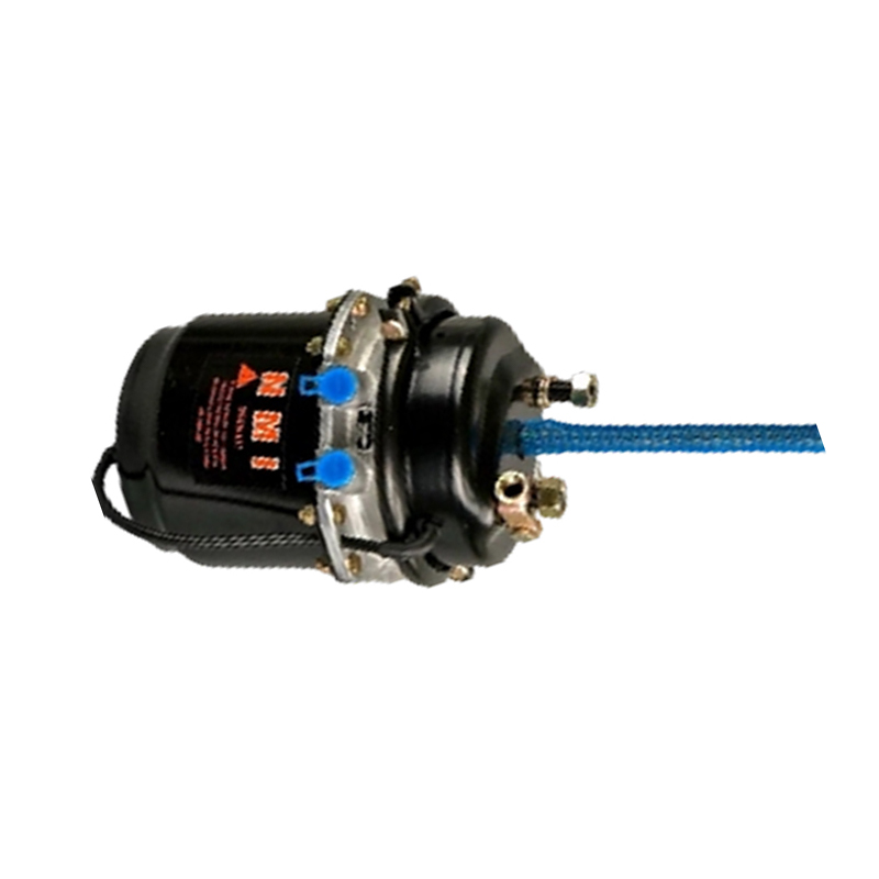 Long-Stroke Brake Chamber for European Commercial VehiclesLong-stroke air brake chamber for European commercial vehicles; check stroke, mounting, port position, and sealing when selecting a replacement.View Product →
For heavy-duty fleets, compare spring brake chambers for heavy-duty trucks by stroke, mounting, port position, and environmental sealing. A chamber that is correct for a mild-duty route may not have the corrosion protection or diaphragm compound needed for winter road salt, high humidity, or frequent wash-down.
ABS, EBS, and Pressure Modulation
ABS and EBS do not replace the pneumatic system. They supervise it. ABS solenoid modulator valves hold, release, or reapply pressure at individual wheels when wheel speed signals indicate an impending lockup. EBS goes further by integrating brake signal transmission, axle modulation, and diagnostic data. A driver may notice a softer pedal, a different release feel, or a warning lamp when an electronic fault is present. The pneumatic valve body, seals, and exhaust path still have to work correctly.
Common electronic-related complaints include a wheel that releases too slowly, a pressure signal that does not match pedal demand, or a warning that appears only after a few brake applications. These faults can come from a sensor, wiring, voltage drop, or a sticking modulator valve. Do not replace the electronic control unit before checking supply voltage, ground quality, connector sealing, and air pressure at the modulator. A dirty or wet connector can mimic a valve failure.
When a modulator is replaced, confirm the voltage rating, connector keyway, port thread, and mounting orientation. Some units look similar but differ in internal hold-and-release timing. A mismatch may not show up in a stationary test; it may appear only during a loaded stop or a low-friction event. Diagnostic trouble codes are useful, but they should be read alongside pressure tests and visual inspection of the pneumatic path.
Parking, Emergency Release, and Trailer Circuits
The parking brake circuit is a pressure-holding circuit. In a spring brake system, releasing the parking brake means supplying enough pressure to compress the spring. Applying the parking brake means exhausting that pressure. If the hand control valve leaks, the spring brake may apply slowly or fail to release fully. If the trailer supply line loses pressure, the tractor protection valve should protect the tractor circuit and signal a trailer emergency condition. These interactions are why a parking brake complaint should be tested with the trailer connected and disconnected.
Trailer circuits add another layer: supply line, service line, glad hands, trailer relay valve, trailer emergency valve, and quick release components. A restricted supply line can cause slow trailer release. A leaking service line can cause the trailer brakes to apply when the tractor is not braking. A damaged glad hand seal can admit water and dirt. The tractor protection valve must be able to close the trailer supply in a breakaway or pressure-loss event without draining the tractor's safe stopping pressure.
Test parking and emergency functions at low speed in a safe area. Confirm that the parking brake holds on a grade, that release is prompt after the control valve is moved, and that the trailer responds within the expected time. Do not rely on a dashboard lamp alone. A lamp can indicate a switch signal while the pneumatic circuit is still slow or partially blocked.
Troubleshooting Matrix for Common Air Brake Complaints
Use complaint patterns to narrow the inspection path, then confirm with pressure gauges and a leak test. The table below is not a substitute for the vehicle service manual, but it helps separate supply-side, control-side, and apply-side faults.
| Complaint | Likely cause | First checks |
|---|---|---|
| Pressure builds slowly after start-up | Compressor wear, restricted intake, leaking discharge line, stuck dryer purge, governor fault | Build-up time, purge behavior, discharge leak, governor signal line, reservoir drain condition |
| Brakes apply late or feel weak | Low reservoir pressure, restricted foot valve inlet, slow relay valve, kinked signal line, chamber stroke issue | Gauge pressure at foot valve inlet and relay outlet, relay exhaust, pushrod stroke, slack adjuster condition |
| Brakes release slowly or drag | Blocked relay exhaust, faulty quick release valve, residual pressure, swollen seals, kinked hose | Release time at each chamber, quick release orientation, exhaust port restriction, residual pressure after pedal release |
| Air leaks at the treadle area | Worn foot valve exhaust seat, contaminated inlet seat, damaged plunger seal | Leak rate with pedal released and applied, treadle free play, inlet air quality, valve repair kit condition |
| Parking brake will not release | Hand control valve leak, low supply pressure, blocked release line, spring brake chamber fault | Pressure at release port, control valve exhaust, chamber caging function, trailer supply interaction |
| Water or oil in reservoirs | Failed dryer cartridge, leaking purge valve, compressor oil carryover, missing drain service | Cartridge age, purge valve seat, wet tank condition, compressor discharge temperature, drain schedule |
| ABS or EBS warning after brake use | Sensor signal, wiring, voltage drop, sticking modulator valve, pressure sensor fault | Supply voltage, ground, connector sealing, wheel speed signal, modulator pressure response |
Pressure Tests That Reveal the Difference Between “Works” and “Works Safely”
A truck can pass a simple “brakes apply” check and still fail a safety test. Static pressure tests should include governor cut-in and cut-out, system leak-down with the engine off and service brakes released, leakage with the pedal applied, and spring brake hold. A common workshop sequence is to build full pressure, shut down, wait for stabilization, and then record pressure loss over a defined period. The exact allowable loss depends on the vehicle specification and test method, so the service manual should set the pass or fail line.
Dynamic checks matter too. At low speed in a clear area, apply the brakes gently and listen for exhaust timing. A delayed hiss or a second release sound can indicate a relay valve or quick release problem. Compare left and right chamber stroke. Check for heat after a short run; a dragging brake will show up as a hot drum or disc before it becomes a driver complaint. On a loaded vehicle, verify that pressure recovers between applications and that the low-pressure warning activates at the specified point.
Build-Up
Time from cut-in to cut-out. Slow build-up points to supply restriction or compressor condition.
Leak-Down
Pressure loss with engine off and brakes released. Isolates reservoir, valve, and line leaks.
Applied Leak
Pressure loss with pedal held. Exposes chamber diaphragms, valve seats, and hose joints.
Release Time
Time for chamber pressure to fall. Reveals exhaust restrictions and sticking release valves.
Maintenance Intervals and the Parts Most Often Replaced Too Late
Brake maintenance is often driven by inspection findings rather than a single calendar interval. Still, some items deserve planned replacement because failure is predictable. Air dryer cartridges, reservoir drains, chamber diaphragms, and valve repair kits are common examples. A cartridge left in service too long can pass moisture until the desiccant is saturated, then release a burst of contamination. A chamber left until the pushrod stroke is far out of range can overheat the foundation brake and damage the slack adjuster.
Inspection should include the air dryer purge, reservoir drains, foot valve free play, relay valve exhaust, quick release valve operation, chamber stroke, hose condition, and glad hand seals. Look for chafed lines near frame brackets and suspension components. Check that all exhaust ports are protected but not blocked by mud, ice, or undercoating. A painted-over exhaust port can cause slow release and is easy to miss after bodywork or refurbishment.
Every Pre-Trip
Build pressure, check warning function, test service brake response, test parking brake hold, drain reservoirs as required.
Periodic Service
Inspect dryer purge, valve exhausts, chamber stroke, hose routing, and leakage. Replace filters and repair kits on condition or schedule.
After Repair
Repeat leak-down, applied leak, release timing, and parking tests. Confirm that no new fitting was over-tightened or left with a mismatched thread.
Seasonal Change
Check dryer heater circuit, drain valves, and freeze protection before cold weather. Confirm that exhaust ports are clear after winter wash-down.
Replacement Selection: Tolerances, Threads, and Real Operating Conditions
Air brake parts often look interchangeable at a glance. The differences sit in port threads, seal compounds, spring rates, diaphragm material, exhaust flow, and voltage. A metric port forced into an NPT fitting can seal at first and then weep after heat cycles. A 12V solenoid installed on a 24V circuit may work briefly and then fail. A chamber with the correct stroke but the wrong mounting clock position can place the port where the hose rubs on a bracket.
For purchasing decisions, build a specification checklist before comparing prices: valve function, circuit count, control pressure, port type and size, mounting pattern, electrical connector, voltage, stroke, chamber type, temperature range, corrosion protection, and service kit availability. In heavy-duty use, the lowest-cost part is rarely the lowest-cost installation if it shortens service life or causes a repeat roadside call. Ask for dimensional drawings, pressure test data, and material information where the application is safety-critical.
Also consider the operating environment. A truck used on salted winter roads needs strong external corrosion protection and sealed connectors. A vehicle on frequent stop-start duty needs stable valve cycling and good exhaust flow. A long-haul tractor benefits from predictable relay valve response and clean air treatment. A trailer fleet should standardize glad hand seals, chamber types, and relay valve service kits where possible to reduce diagnostic confusion across the fleet.
FAQ: How a Truck Air Brake System Works in Service
Why does a truck use air instead of hydraulic fluid?
Air is compressible, available, and can be stored in reservoirs for multiple applications. It also allows a spring brake to apply when pressure is lost, which provides a fail-safe parking and emergency function. The trade-off is that air systems need dryers, leak control, and careful valve timing.
What happens when one brake circuit fails?
A dual-circuit foot valve and circuit protection valve are designed to isolate the failed circuit and preserve pressure in the remaining circuit. The driver may notice longer pedal travel, a warning, or reduced braking performance. The vehicle should be stopped safely and inspected before further use.
Why do brakes release slowly after the pedal is released?
Slow release usually points to restricted exhaust flow, a sticking relay valve, a faulty quick release valve, residual pressure, or a collapsed hose. Check release time at the chamber and inspect exhaust ports before replacing the foot valve.
How does a spring brake chamber work?
A large spring applies the parking brake when air pressure is removed. Normal air pressure compresses the spring and holds it off. If system pressure drops below a safe level, the spring applies the brake automatically. Service procedures must respect the stored spring energy.
Can an air dryer fault affect brake response?
Yes. Moisture and oil can cause valve seats to stick, seals to swell, and exhaust ports to freeze. A dryer fault may first appear as slow release, uneven application, or water in the reservoir rather than a complete brake failure.
What should be checked after replacing an air brake valve?
Confirm port thread compatibility, leak-free joints, correct hose routing, full pedal travel, release timing, and parking brake function. Repeat leak-down and applied-pressure tests. A valve that passes a static test should still be checked at low speed for modulation and release behavior.
Our Main Products
Copyright © Zhejiang Gongzheng Machinery Co., Ltd. All Rights Reserved.
