


Gongzheng
Gongzheng
Gongzheng
Gongzheng
Gongzheng
Gongzheng
Gongzheng
Gongzheng
Gongzheng
Gongzheng
Gongzheng
Gongzheng
Gongzheng
Gongzheng
Gongzheng
Gongzheng

Industry News
Where Is the Air Dryer Located on a Semi? Full Location Guide and Maintenance Tips

Content
- 1 Where Exactly Is the Air Dryer Mounted on a Semi?
- 2 Why Truck Engineers Put the Air Dryer on the Frame Rail
- 3 Where the Air Dryer Sits in the Semi Air Brake System
- 4 How to Identify the Air Dryer on Your Semi
- 5 Air Dryer Components You Can See From the Mounting Position
- 6 Common Warning Signs That the Air Dryer Needs Attention
- 7 Air Dryer Maintenance and Cartridge Replacement
- 8 What to Look for When Choosing an Air Dryer or Replacement Cartridge
- 9 Frequently Asked Questions About Semi Air Dryer Location and Function
- 9.1 Can I drive a semi if the air dryer is clogged?
- 9.2 Why do I still see water in the air tanks after installing a new air dryer?
- 9.3 Should the air dryer be mounted vertically or horizontally?
- 9.4 How often should a semi air dryer purge?
- 9.5 Can I replace only the cartridge instead of the whole air dryer?
- 9.6 A used semi I bought has its air dryer mounted on a rear crossmember between the frame rails. Is that a problem?
Find the thickest, hottest air line running from the semi's air compressor and follow it along the engine. At the end of that line, bolted to the outside of a frame rail with a steel or aluminum bracket, you will see a cylindrical canister roughly the size of a large coffee pot. That canister is the air dryer. On a typical North American convention-cab tractor, this assembly is on the left-hand frame rail just behind the engine bay or beneath the cab skirt. On European cab-over trucks, it is commonly on the right-hand frame rail behind the cab steps. On vocational trucks, it may be tucked behind a body subframe, but the rule is consistent: the air dryer sits between the compressor discharge and the wet tank, as close to both as packaging allows.
This location is not an accident. It directly affects how well the desiccant dries compressed air, how reliably the purge cycle regenerates the drying bed, how easily a mechanic can replace the cartridge, and how long the rest of the air brake system lasts. Knowing the exact mounting point also helps you inspect a used truck before purchase, diagnose water-in-air complaints, plan cartridge replacements, and understand why a repair shop may have solved a purge-cycle problem incorrectly.
Where Exactly Is the Air Dryer Mounted on a Semi?
The majority of heavy-duty air dryers are bolt-on assemblies that attach to the vertical face of the frame rail, just behind the engine bay. The mounting bracket is typically a steel stamping or an aluminum bracket that wraps around the cylindrical body near its base and is secured with two or four bolts. Several brackets include rubber isolation bushings to reduce vibration from the chassis; those bushings are the reason a dryer body often feels slightly loose if you push it by hand even when the bolts are correctly torqued.
In terms of forward-to-rear position, the dryer is located between the back of the engine and the forward end of the rear suspension. On a day-cab truck, you can stand between the cab sill and the steer axle and see the canister directly. On a sleeper truck, the dryer may sit farther rearward, under the sleeper fairing, but it remains on the frame rail and not on the engine block itself.
The left-versus-right question is decided by the compressor mounting. Most heavy-duty diesel engines used in semis drive the air compressor from a gear train or an accessory drive on one side of the block. The dryer must be within a short pipe run of that compressor discharge port, so it is almost always on the same side. If the compressor is on the left side of the engine, the dryer is on the left frame rail; if the compressor is on the right, the dryer follows to the right. In a small number of trucks, the compressor is driven from the rear gears, and the dryer may sit on the opposite rail next to the wet tank.
Vertical mounting is the overwhelming standard because the purge valve and exhaust port must remain at the lowest point. Horizontal mounting exists only on specific chassis and only with dryer models designed for that orientation. Never lay a vertically-designed dryer flat when you install a replacement, because the desiccant bed will shift and the purge valve will not drain.
| Truck platform | Usual air dryer location | Notes for technicians |
|---|---|---|
| North American convention-cab tractor | Left-hand frame rail, just behind the engine or under the cab skirt | Vertical mount; wet tank is normally on the same rail; cartridge replacement does not require lifting the cab |
| European cab-over or flat-front tractor | Right-hand frame rail, behind the cab steps or under the cab rear panel | Short discharge line; heated dryers are common for cold climate operation |
| Vocational or construction truck | Passenger-side frame rail, sometimes inside a body access bay | Horizontal adapter kits exist; verify that the purge port still points downward after installation |
| Older truck with a retrofit air dryer | Frame rail, whichever side has open space ahead of the wet tank | Bracket holes may be drilled; keep the dryer at least 300 mm from exhaust piping |
Why Truck Engineers Put the Air Dryer on the Frame Rail
Three engineering goals explain the frame-rail location: protect the desiccant, protect the purge function, and protect the technician who services it.
The first goal is heat management. Compressed air leaving a heavy-duty compressor can exceed 200°C at the cylinder head. If the dryer were bolted directly to the engine valve cover or mounted close to the exhaust manifold, the desiccant bed would saturate with moisture much faster because adsorption capacity decreases as bed temperature rises. The frame-rail position moves the dryer away from primary heat sources and gives the discharge line enough length to let the air cool partially before entering the bed. A cooler bed reaches lower pressure dew points, which is what actually dries the air for the brake system.
The second goal is consistent purge behavior. A dryer regenerates by releasing a small stored volume of dry air backward through the desiccant bed and out of the purge valve at the bottom. This happens once per compressor unload cycle. The volume of the discharge line and the internal purge reservoir are part of the design calculation. When the dryer is bolted close to the compressor, the purge event is sharp and short. If a dryer is located too far away, the purge air has to push through a long line before it reaches the purge valve, which weakens the regeneration and can leave moisture in the bed.
The third goal is service access. The desiccant cartridge is a wear item that needs replacement every couple of years. Frame-rail height places the canister at waist level when the truck is on a lift, which means one technician can remove the cartridge without removing the cab, the battery box, or the fender. Wet-tank drains are also on frame rails, so the dryer location keeps the weekly moisture check in the same walk around the truck.
The frame-rail position also protects the unit from road debris. The outer face of the rail is exposed to stones and splash, but the inner side of the rail carries brake lines and wiring that would be damaged by a leaking purge port. Placing the dryer on the outer face keeps oil and water discharge away from electrical harnesses and allows air circulation around the canister so the heater and thermostat do not overheat.
Where the Air Dryer Sits in the Semi Air Brake System
Understanding the position of the air dryer is easier when you see the whole air supply path. The charging circuit begins at the compressor and ends at the brake valves, and the dryer is the point where the air passes from the hot, dirty, wet side to the clean, dry side.
Compressor > Discharge Line > Air Dryer > Wet Tank
Wet Tank > Primary Tank > Service Brake Circuits
Wet Tank > Secondary Tank > Parking Brake and Trailer Supply
Air is compressed in the compressor and pushed through a discharge line to the dryer inlet. The dryer removes oil droplets in a coalescing filter stage, removes water vapor in a desiccant bed, and then sends clean air through an outlet check valve to the wet tank. From the wet tank, air flows through check valves into the primary and secondary reservoirs that feed the brake circuits.
The purge cycle works like this: when the brake system reaches the governor cut-out pressure, the compressor stops compressing. At that moment, the dryer releases a small amount of stored dry air that travels backward through the desiccant bed and escapes through the purge valve, blowing out the oil and water that had accumulated on the filter stage and in the sump at the bottom. If you stand near a semi that has just reached full pressure, the single short puff of air from the bottom of the dryer is the regeneration event.
| Parameter | Typical value |
|---|---|
| Governor cut-in pressure | 96-115 psi |
| Governor cut-out pressure | 120-135 psi |
| Purge volume of the air dryer | 0.3-1.0 L depending on the dryer size |
| Maximum working pressure of the dryer | 150 psi (10.3 bar) |
| Recommended desiccant replacement interval | 2 years or 200,000 km in normal climates |
How to Identify the Air Dryer on Your Semi
If you are new to a truck or examining a used vehicle for the first time, there are four visual cues that tell you the canister you are looking at is the air dryer rather than an oil filter, a fuel filter, or a hydraulic reservoir.
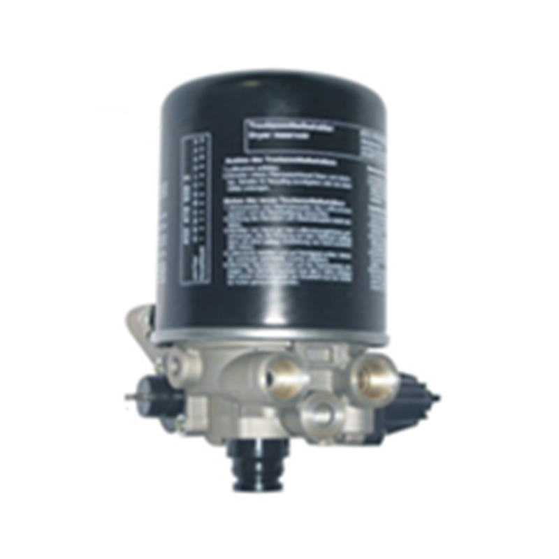
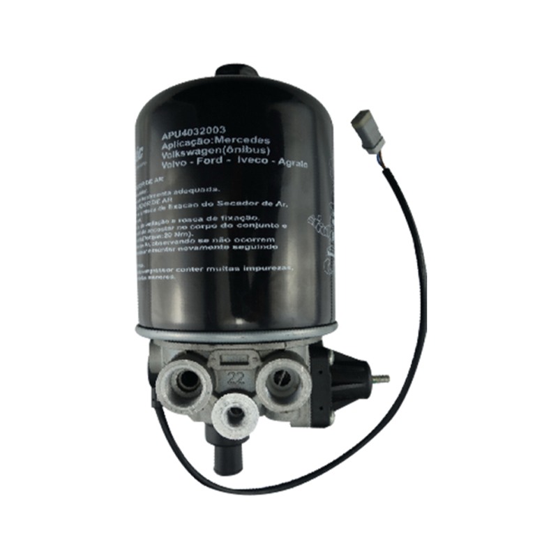
Cylindrical metal body
Steel or aluminum canister with a stamped or cast end cap. It is larger than the spin-on oil filters on the engine and usually has a part number printed on the end cap.
Purge exhaust at the bottom
A slotted port or small threaded exhaust with a rubber or steel discharge tube. No other component on the truck puffs a short blast of air from its base when pressure reaches cut-out.
Discharge line from the compressor
The largest-diameter air line leaving the compressor terminates at the dryer inlet port. Sometimes this line has a heat shield around it where it passes the exhaust.
Clean, cooler outlet to the wet tank
The line leaving the outlet side of the dryer goes directly to the wet tank. This line feels cooler to the touch than the discharge line and carries no oil film when the dryer is healthy.
Most dryers have the part number, the maximum pressure rating, and the flow rating stamped or screen-printed on the end cap. That information is essential when you order a service kit or a replacement cartridge. Write it down before you clean the cap, because the printing can wear off after a few steam washes.
Air Dryer Components You Can See From the Mounting Position
The frame-rail location gives you a good view of almost every serviceable part of the dryer before you disconnect anything. The table below lists the components you can inspect from this position.
| Component | Position relative to the dryer | Function |
|---|---|---|
| Desiccant bed | Inside the cylindrical body | Adsorbs water vapor from compressed air until saturation, then is regenerated by the purge cycle |
| Oil coalescing filter | Inlet side of the desiccant bed | Removes compressor oil droplets and solid particles before air passes through the desiccant |
| Purge valve | Bottom of the canister | Releases stored dry air during regeneration and drains collected oil and water from the sump |
| Outlet check valve | Outlet port or inside the end cover | Prevents wet-tank air from flowing backward into the dryer during the purge event |
| Heater and thermostat | End cover with feed wires | Keeps the purge valve and internal passages above freezing in low ambient temperatures |
| Mounting bracket | Base of the body | Supports the canister and isolates vibration from the frame rail |
If the dryer is a heated unit, check the heater leads during cold-season inspections. A typical heater draws 10 to 18 amperes when energized at 12 volts. Measure the resistance between the two heater leads: a few ohms is normal, zero indicates a shorted element, and infinite resistance indicates an open heater. Replace the end cover assembly if the heater fails, because a frozen purge valve will make the entire charging system build pressure slowly and may even cause compressor failure.
Common Warning Signs That the Air Dryer Needs Attention
Air dryers fail gradually, and the first symptoms are often noticed by the driver before they are noticed by a mechanic. Here are the most frequent warning signs and what each one tells you about the state of the unit.
Water or oil in the wet tank drain. When you open the wet tank drain valve and water shoots out before compressed air, the desiccant bed is saturated or the outlet check valve inside the dryer is leaking. A healthy dryer should keep the wet tank nearly dry, although a few drops of water on a humid morning after a long idle period can be normal.
Compressor runs longer than it used to. A cartridge that is clogged with compressor oil increases the pressure drop across the dryer. As a result, the wet tank pressure rises slowly and the compressor stays in the loaded state longer. This can also be caused by a leak in the discharge line or a failing compressor ring, so check the dryer first and then check compressor output.
A constant small hiss from the purge port. The purge port should only release air during the momentary regeneration at governor cut-out. If it hisses continuously, the purge valve seat is contaminated or the internal check valve is stuck open. This is a common winter failure because ice crystals hold the valve open.
No purge sound at all. If you watch the pressure gauge climb to the cut-out value and the dryer does not puff, the purge valve is stuck closed, the heater circuit is dead in freezing conditions, or the cartridge is completely plugged. A dryer that never purges cannot regenerate, which means the desiccant becomes exhausted after a short time and wet air enters the tanks.
Frost or ice visible around the base of the canister. Ice formation points to a heater failure or a purge valve blocked by debris. When the purge port cannot open, the small amount of water that collects inside the sump freezes and expands, eventually cracking the end cover.
Oil film on the frame rail below the dryer. A light oil film directly beneath the purge port is normal over time, but a heavy film that attracts dust and spreads behind the bracket means the compressor is passing too much oil and the coalescing stage of the dryer is overloaded.
Quick check 1: wet tank drain
Open the wet tank drain for one full second. A healthy dryer means the discharge is mostly air. If water leads the discharge, start diagnosis at the dryer.
Quick check 2: one purge per cycle
Run the engine until the governor cuts out. The dryer should release one clear puff of air. Repeated small hisses or a complete silence are both abnormal.
Quick check 3: outside of the canister
Look for rust blisters, oil weeping from the end cover seam, or a dented body. Any of these conditions suggest that the cartridge is older than its useful life.
Air Dryer Maintenance and Cartridge Replacement
Most air dryer manufacturers recommend a new desiccant cartridge every two years or every 200,000 km, approximately 120,000 miles, for highway operations. Trucks working in humid coastal areas, in dusty environments, or on low-quality compressor oil experience shorter intervals. The most reliable signal is the wet tank drain check described above: if water appears earlier than the interval, replace the cartridge immediately.
Cartridge replacement is a straightforward job when the dryer is on the frame rail. Plan the process around a fully depressurized system and a clean work area around the canister.
- Park the truck on level ground, apply the parking brake, and drain the air system completely to 0 psi. Drain the wet tank, the primary tank, and the secondary tank to be certain no residual pressure remains in the lines.
- Disconnect the heater wires if the dryer has an electric heater. Tag the connections so you can reattach them to the correct terminals.
- Remove the old cartridge with a filter strap. Turn the cartridge counterclockwise looking from above. If it will not move, apply steady pressure to the cartridge body with a strap wrench, never to the purge port or the end cover.
- Clean the exposed end cover threads and the sealing surface with a lint-free cloth. Look for hairline cracks, corrosion pitting, or stripping in the threaded area. A cracked end cover is a reason to replace the entire dryer housing.
- Install the new O-rings from the service kit and lubricate them with clean silicone grease. Do not use grease that contains petroleum solvents, because those attack the rubber.
- Spin on the new cartridge and tighten it to the torque range indicated on the package, typically 30 to 35 foot-pounds. Overtightening distorts the O-ring and can crack the end cover.
- Reconnect the heater wires and verify the connection is secure. If the dryer has an internal governor or a separate governor line, check that the small hose is not pinched by the new cartridge.
- Close all drains, pressurize the truck, and watch the gauge. At governor cut-out, confirm that the dryer emits one purge pulse. Check the end cover and line fittings with soapy water for leaks.
While the cartridge is off, check the two bracket bolts that hold the dryer to the frame rail. A typical torque value is 45 to 60 foot-pounds for the frame-rail side and 20 to 30 foot-pounds for the clamp side, but the figures printed on the bracket label take priority. Inspect the discharge line for heat cracks and for areas where it rubs against the frame, a battery box, or a wire harness. A chafed discharge line is a common source of air loss that is often mistaken for a dryer fault.
What to Look for When Choosing an Air Dryer or Replacement Cartridge
Air dryers from different manufacturers can look identical from the outside, but the internal filling and the quality of the seals vary significantly. Since the dryer protects every downstream valve in the brake system, the small differences in materials become large differences in maintenance cost.
The desiccant bed should be a blend of activated alumina and molecular sieve. Activated alumina alone can remove a reasonable amount of moisture at normal temperatures, but a molecular sieve pulls the air to a lower pressure dew point at the flow rates that a semi brake system actually uses. A cartridge that lists only one type of desiccant is usually a lower-performance product. If you are comparing two cartridges, ask for the weight of the desiccant; a heavier fill is not automatically better, but it is a sign that the maker has not cut corners on bed volume.
Check the inlet and outlet port sizes against the existing plumbing on your truck. Replacement dryers sometimes come with ports configured for a different thread size or a different orientation, especially when the same body is sold across several vehicle platforms. A dryer that requires a new adapter fitting or a rerouted discharge line will cost more to install than the price of the part itself.
For trucks that operate in cold regions, choose a heated dryer with a voltage that matches the truck electrical system. Most heavy-duty trucks use 12 or 24 volts; identify which one your chassis uses before ordering. The heater circuit should be controlled by a thermostat that switches on only when the ambient temperature approaches freezing, not a permanent draw that wastes energy.
Inspect the purge valve design before you buy. A solid purge valve has a hardened seat, a stainless steel spring, and a discharge port that can be cleaned without disassembling the whole valve. These details determine whether the dryer will still purge at low temperatures after two years of service.
Finally, consider the manufacturing process behind the unit. Components that come from IATF 16949-certified production lines tend to have more consistent castings, seal surfaces, and O-ring compounds than parts from uncertified sources. If a factory answers technical questions with specific numbers for desiccant weight, outlet check valve opening pressure, and purge volume, that is a stronger signal than a generic warranty promise. A semi air dryer is a safety component; its internal quality is not a place to save money.
Frequently Asked Questions About Semi Air Dryer Location and Function
Can I drive a semi if the air dryer is clogged?
You can drive temporarily, but not without risk. A clogged dryer allows moisture and oil to enter the air tanks, corrodes the brake valves from inside, and can cause ice formation that locks the brakes in winter. The compressor also runs longer cycles, which shortens its life. Treat a clogged dryer as a same-day repair, not a scheduled maintenance item.
Why do I still see water in the air tanks after installing a new air dryer?
The usual causes are a leaking outlet check valve in the dryer, a purge valve that does not open at cut-out, or a compressor that passes oil through worn rings. Sometimes the new cartridge was installed with a damaged O-ring, allowing wet air to bypass the desiccant bed. Check the purge function first, then drain the tanks completely and repeat the test after a full brake application.
Should the air dryer be mounted vertically or horizontally?
Vertically unless the dryer model is specifically designed for horizontal use. The purge valve must be the lowest point of the assembly so that water and oil drain out of the sump. Laying a vertical-designed dryer flat will let the desiccant settle unevenly, block the purge port, and eventually turn the desiccant into a muddy mass.
How often should a semi air dryer purge?
Once per compressor unload cycle. Under normal driving on a highway with few brake applications, that may be every several minutes. In heavy traffic with constant brake use, the compressor will load and unload more often, so the dryer will purge more frequently. Rapid repeat purging every few seconds means there is an air leak downstream or the governor settings are wrong.
Can I replace only the cartridge instead of the whole air dryer?
In most cases, yes. The housing, bracket, and internal valves are designed to last several cartridge intervals. Replace the cartridge, the O-rings, and the purge valve if it has been in service for more than 500,000 km or is leaking. If the heater circuit is open, the end cover is cracked, or the mounting foot has a fatigue fracture, replace the entire unit.
A used semi I bought has its air dryer mounted on a rear crossmember between the frame rails. Is that a problem?
It may be a retrofit installation or a rare chassis layout, and it can still work correctly. Confirm three things: the dryer is downstream of the compressor and upstream of the wet tank; the purge port is the lowest point of the canister; and the outlet check valve holds pressure. If all three are true, the installation is acceptable even though it looks different from the factory default.
Our Main Products
Copyright © Zhejiang Gongzheng Machinery Co., Ltd. All Rights Reserved.
