Core Reconstruction: Brake Leveling Valve and Its Role in Vehicle Dynamics
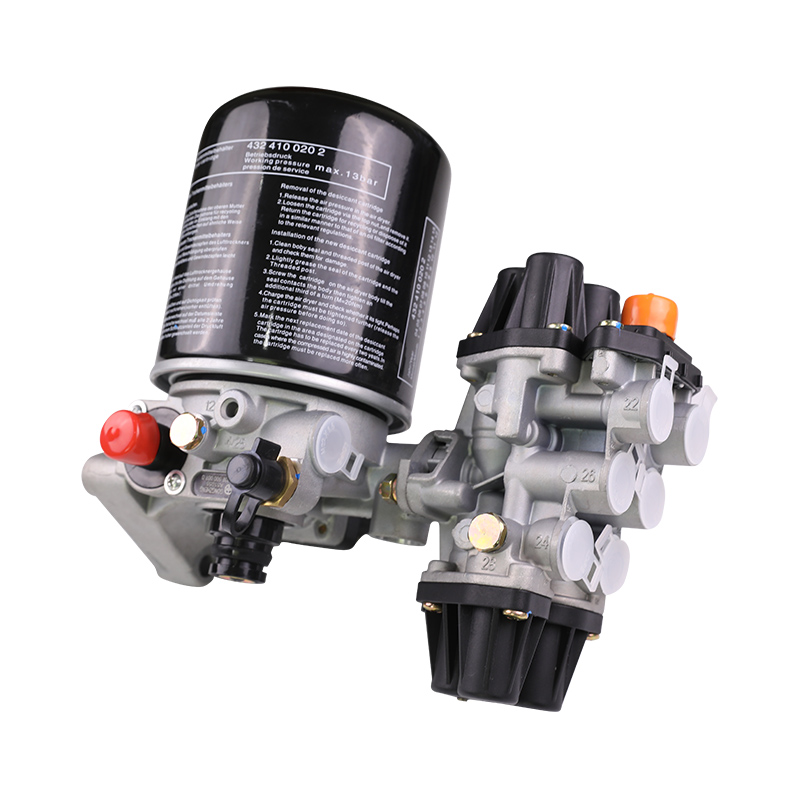
In modern commercial transportation and advanced passenger bus engineering, the Brake Leveling Valve (commonly referred to as a Height Control Valve or HCV) is not merely a simple pneumatic component; it is the "brain" and "sensory organ" of the entire air suspension system. Its core function is to sense changes in vehicle load and automatically adjust the pressure within the air springs (airbags), thereby maintaining a constant design height of the vehicle body relative to the axle.
This constant height is not just for aesthetics; it is directly related to vehicle dynamics. When a heavy truck transitions from empty to fully loaded, without the intervention of the Brake Leveling Valve, the massive gravitational force would cause the suspension to bottom out. This would not only damage the chassis structure but also completely destroy the vehicle's handling stability. The valve senses the displacement between the frame and the axle through a mechanical linkage, precisely controlling the flow of compressed air.
Static and Dynamic Balance
The Brake Leveling Valve must operate in two entirely different environments:
Static Compensation: During loading or unloading, as the load slowly increases or decreases, the valve counteracts displacement by inflating or exhausting air, ensuring the cargo floor remains level with the loading dock.
Dynamic Response: While driving at high speeds, the vehicle encounters road irregularities. A high-quality Brake Leveling Valve must possess a "filtering" function. Through an internal delay mechanism, it avoids frequent inflation and exhaustion caused by momentary bumps, thereby saving compressed air and extending the life of the air compressor.
Core Functions and Contribution to the Braking System
Although its name contains the word "Brake," its role is indirect yet profound. By maintaining a level body, it ensures:
Load-Sensing Proportioning Control: On vehicles equipped with mechanical brake proportioning valves, the height reference provided by the Brake Leveling Valve is critical data for distributing braking force between the front and rear axles.
Prevention of Brake Dive: A stable suspension height improves the center of gravity shift during emergency braking, preventing front-wheel overload and subsequent braking efficiency decay.
Tire Grip Optimization: By maintaining the optimal working stroke of the air springs, it ensures the tires achieve maximum contact area under various road conditions.
Core Technical Parameter Comparison: Mechanical vs. High-Performance Electronic
To better understand the performance differences of the Brake Leveling Valve, the following table compares the parameter logic of traditional mechanical control valves with modern high-performance electronic control systems (ECAS/ELC):
| Performance Dimension | Standard Mechanical Brake Leveling Valve | Electronic Control System (ECAS/ELC) |
| Static Accuracy | +/- 5 mm to +/- 10 mm | +/- 1 mm to +/- 3 mm |
| Response Delay (Deadband) | Mechanical damping, usually 3-8 seconds | Software controlled, real-time (0.1s - 20s) |
| Air Consumption | Higher (due to mechanical fluctuations) | Extremely low (intelligent filtering) |
| Operating Pressure Range | Up to 12 Bar - 13 Bar | Up to 15 Bar |
| Temperature Range | -40 degrees C to +80 degrees C | -40 degrees C to +100 degrees C |
| Flow Capacity | 150 - 400 L/min (depends on port) | Variable and larger flow range |
| Maintenance Complexity | Low (mechanical linkage checks) | High (requires diagnostic software) |
Physical Mechanism and Working Principle: How the Brake Leveling Valve "Thinks"
The operational logic of the Brake Leveling Valve is based on a simple physical feedback loop: Load -> Displacement -> Air Path Distribution.
1. Lever Feedback Principle
The valve body is typically mounted on the chassis frame, while one end of the adjustment linkage is connected to the axle. When the vehicle is loaded, the frame sinks relative to the axle, causing the linkage to rotate upward. This mechanical rotation, through an internal cam or eccentric shaft, pushes the valve core away from the neutral position.
2. Three-Way Control Logic
Intake Phase: When the linkage moves upward beyond the set "deadband," the intake port opens. Compressed air from the reservoir flows into the air springs, increasing support force and pushing the frame back to its original height.
Neutral Phase (Deadband): Once the frame returns to the set height, the linkage returns to a horizontal position. Both intake and exhaust ports are closed. The width of this zone (usually around an 18-degree swing angle) determines the sensitivity of the valve.
Exhaust Phase: When the load is reduced (unloading), the air springs have excess lifting force, causing the frame to rise. The linkage rotates downward, opening the exhaust port to release excess pressure.
3. The Science of Delay Mechanisms
To prevent the valve from blindly inflating or exhausting when driving over speed bumps, high-performance Brake Leveling Valves feature internal hydraulic or mechanical damping. This damping ensures that only displacement changes lasting longer than a set number of seconds (such as load changes) trigger pneumatic action, while high-frequency road vibrations are "ignored." This protects the valve itself and ensures the stability of the air reservoir pressure, which is vital for braking system safety.
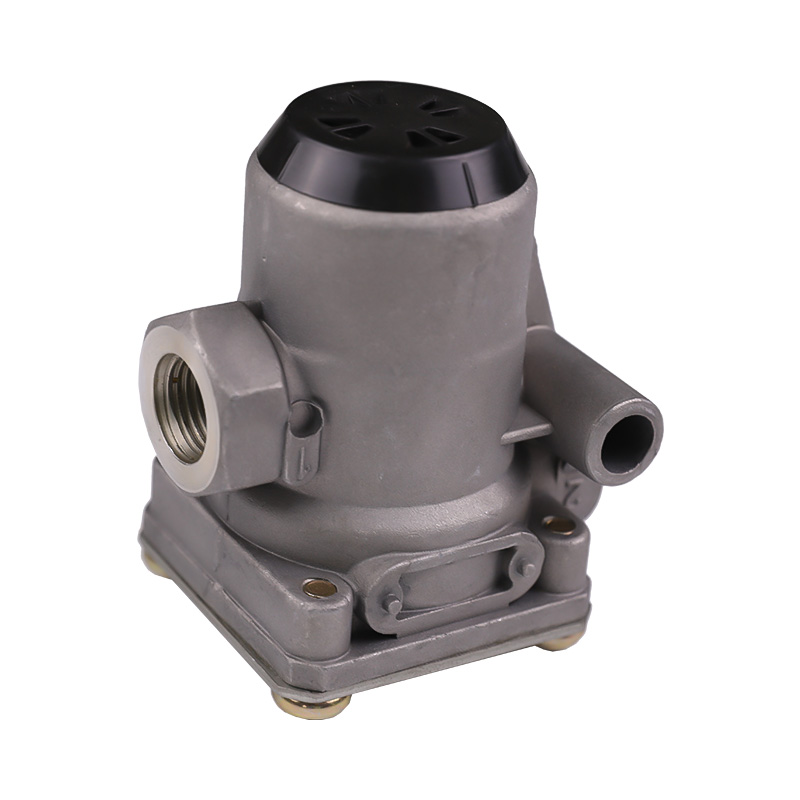
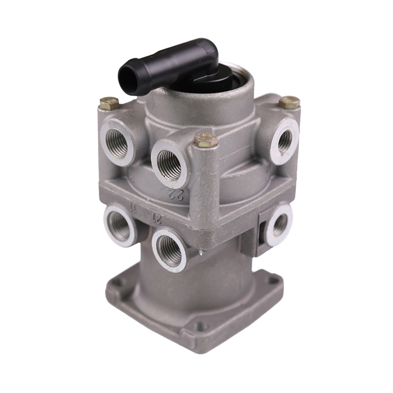
Core Component Analysis: Precision Engineering Construction
The performance of a Brake Leveling Valve stems from the synergy of its internal precision components. Since this part is directly exposed to harsh under-chassis environments, its material selection must follow high industrial standards.
1. Valve Body
The valve body is the base of the entire assembly, usually made of high-strength die-cast aluminum alloy or engineering plastics (such as polyamide reinforced fiber).
Aluminum Alloy Body: Provides excellent structural strength and pressure resistance, capable of withstanding system burst pressures up to 15 Bar.
Anodizing Treatment: To combat chemical corrosion from road de-icing agents, the surface is usually deep-anodized to ensure no perforation corrosion occurs during over 500 hours of salt spray testing.
2. Internal Pistons and Seals
This is the most delicate and core part of the Brake Leveling Valve.
Dynamic Seals: Typically made of EPDM (Ethylene Propylene Diene Monomer) or HNBR (Hydrogenated Nitrile Butadiene Rubber). These materials maintain elasticity at -40 degrees C to prevent internal air leaks.
Self-Lubricating Coating: Piston surfaces are often coated with PTFE (Teflon) to reduce reciprocating friction, ensuring smooth response even to minute displacements.
3. Adjustment Linkage and Bushings
The linkage transmits height changes to the valve core.
Adjustable Linkage: Made of stainless steel or galvanized steel with threaded adjustment capabilities for fine-tuning the vehicle's nominal height during installation.
Flexible Bushings: Rubber bushings at both ends of the linkage act as buffers, absorbing high-frequency vibrations to prevent mechanical impact from damaging the internal valve structure.
Classification and Application Scenarios
The Brake Leveling Valve is divided into several mainstream types based on control logic and vehicle application.
1. Mechanical vs. Electronic Control
Mechanical: The classic design, driven entirely by physical displacement. Advantages include no reliance on electricity and simple maintenance; it is the first choice for heavy trailers and conventional trucks.
Electronic (ECAS): Uses displacement sensors instead of linkages and controls air paths via solenoid valves. Though complex, it allows for one-touch lifting/lowering and independent multi-axle adjustment.
2. Parameter Logic Comparison in Different Conditions
| Application | Priority Parameter | Valve Characteristic |
| Tractor | Response speed & Stability | Requires strong filtering/delay to prevent misadjustment during acceleration or braking. |
| Trailer | Flow rate & Durability | Focuses on rapid inflation/exhaust (large ports) to handle massive load changes during loading. |
| City Bus | Precision & Smoothness | Requires an extremely narrow deadband to ensure no perceptible height change as passengers board. |
| Off-road | Impact resistance & Sealing | Thicker valve body; intake/exhaust ports usually equipped with dust-proof check valves. |
Key Performance Indicators and Testing Standards
A qualified Brake Leveling Valve must pass rigorous quantitative tests before leaving the factory.
1. Flow Rate
The flow rate determines how quickly the suspension recovers its height.
Intake Flow: At a standard pressure of 7 Bar, high-performance valves typically have an intake flow between 300 and 500 L/min.
Exhaust Flow: To prevent the vehicle from bouncing too quickly after unloading, the exhaust flow is usually maintained around 250 L/min.
2. Deadband Range
This is the core indicator for measuring precision.
Standard Range: Usually set between +/- 2 degrees to +/- 4 degrees of lever swing.
Significance: If the deadband is too narrow, slight vibrations during driving will trigger the valve; if it is too wide, the height won't return accurately after load changes.
3. Actuation Torque
To ensure minute load changes can drive the valve, the actuation torque is typically required to be less than 1.5 Nm. This requires micron-level precision in the cam mechanism and seals.
4. Durability Testing
Cycle Life: Under simulated road conditions, the valve must pass at least 1,500,000 full-stroke cycles, with the internal leakage rate increase not exceeding 10% of the initial value.
Installation, Calibration, and System Integration
The performance of the Brake Leveling Valve depends not only on its manufacturing but also on its geometric installation accuracy.
1. Geometric Logic of Installation
The valve is mounted on the chassis frame, while the linkage connects to the center of the axle.
Horizontal Reference: When the vehicle is at its nominal empty height, the linkage should be as horizontal as possible.
Leverage Ratio: The effective length of the linkage directly affects sensitivity. A shorter linkage increases the valve's reaction sensitivity.
2. Standard Ride Height Calibration
This is the most critical step in the installation process.
Calibration Flow: Adjust the threads of the adjustable linkage until the vehicle automatically stops at the manufacturer's required "nominal height" under specified air pressure.
Error Limits: For multi-axle vehicles, the height deviation between left and right Brake Leveling Valves usually should not exceed 5 mm.
3. Synergy with Braking and Safety Systems
Load Sensing Signal: In pure pneumatic systems, the pressure in the air springs (controlled by the height valve) is sent directly to relay or proportioning valves as control pressure for braking.
Stability Control (ESC/RSS): The center of gravity balance maintained by the Brake Leveling Valve is the foundation for these algorithms.
### Troubleshooting: When the Brake Leveling Valve Fails
Identifying early failures can prevent serious road accidents.
| Symptom | Potential Cause | Diagnosis Suggestion |
| Vehicle Lean | Linkage detached on one side or inconsistent deadband | Check if linkages are of equal length; check for worn ball joints. |
| No Inflation | Clogged intake filter or stuck internal valve core | Disconnect intake fitting to check for carbon buildup or ice. |
| Constant Small Exhaust | Worn valve core seals or corroded internal seat | Apply soapy water to the exhaust port to check for continuous bubbles. |
| Slow Adjustment | High viscosity of damping fluid or high piston friction | Check the air dryer efficiency. |
| Over-inflated Springs | Linkage installed backward or blocked exhaust port | Check if the exhaust silencer or dust cap is sealed by mud. |
Maintenance and Optimization Strategies
1. Air Quality Control (Core Strategy)
Moisture and oil in compressed air are the enemies of the Brake Leveling Valve.
Moisture: Freezing in low temperatures can lock the valve core.
Oil: Oil bypass from the compressor can degrade EPDM seals, causing material swelling.
Suggestion: Check air dryer cartridge effectiveness every quarter.
2. Lubrication of Mechanical Linkage
Ball Joint Care: Keep ball joints at both ends of the linkage clean and periodically spray with a non-petroleum-based lubricant.
Clean Exhaust Port: Ensure the exhaust port "breathes" freely to prevent backpressure from confusing the valve logic.
3. Part Replacement Principles
When replacing a Brake Leveling Valve, ensure the following parameters match the original:
Flow Rating: Never use a low-flow valve on high-displacement axles.
Delay Time: Must match the filtering frequency of the chassis design.
FAQ
Q1: How can I quickly check if the Brake Leveling Valve is working without professional tools?
Answer: With the vehicle idling and air pressure sufficient, have two adults stand on the rear tailboard. If you hear a distinct intake sound (after a 5-10 second delay) and the vehicle rises slowly, the static response is normal.
Q2: Why are Brake Leveling Valves more prone to failure in winter?
Answer: Primarily due to condensation freezing in the air lines. Ice crystals block the delicate movement of the valve core or clog the tiny exhaust ports. It is recommended to replace the air dryer before winter.
Q3: What happens if I change the length of the linkage?
Answer: Changing the length alters the "balance zero point" of the vehicle. This leads to air springs being chronically over-inflated (stiff ride, risk of bursting) or under-inflated (frequent bottoming out against limit blocks).
Q4: Does the loudness of the "exhaust sound" indicate performance?
Answer: No. The loudness depends on the presence of an exhaust silencer and the flow rate. A sudden loud exhaust is a normal reaction to load unloading, but a continuous hissing indicates a seal failure.