Introduction
In the intricate world of heavy-duty vehicles, every component plays a crucial role in ensuring safe and efficient operation. Among these, brake chambers stand out as indispensable elements of the air brake system. These seemingly simple devices are the unsung heroes that translate the driver's intention to stop into the physical force required to bring massive trucks, buses, and other commercial vehicles to a halt. Without properly functioning brake chambers, the entire air brake system—and thus, the safety of the vehicle and its occupants—would be severely compromised. This guide will delve into the critical role of brake chambers, exploring their types, how they function, and essential maintenance practices to ensure optimal performance and safety.
What is a Brake Chamber?
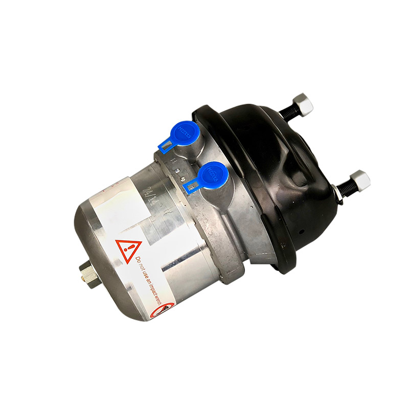
A brake chamber, often referred to as an air brake chamber or truck brake chamber, is a vital component of a heavy-duty vehicle's air brake system. Its primary function is to convert the pneumatic energy (compressed air) from the air brake system into mechanical force. This mechanical force is then used to actuate the vehicle's brakes, slowing or stopping it.
At its core, a brake chamber consists of a sealed housing that encloses a flexible diaphragm. On one side of the diaphragm, compressed air is introduced, while the other side is connected to a pushrod. When air pressure builds up in the chamber, it exerts force on the diaphragm, causing it to flex and push the connected pushrod outwards. This outward movement of the pushrod is the mechanical force that ultimately applies the brakes. The pushrod, in turn, connects to a slack adjuster, which then rotates the S-cam (in S-cam brakes) or directly applies pressure to the brake shoes, engaging the braking mechanism.
The main components of a brake chamber include:
Housing: The durable outer casing that encloses and protects the internal components.
Diaphragm: A flexible rubber or synthetic membrane that moves in response to air pressure.
Pushrod: A rigid rod attached to the diaphragm that transmits the mechanical force to the slack adjuster.
Return Spring: (In service chambers) A spring that pulls the diaphragm and pushrod back to their resting position when air pressure is released.
Types of Brake Chambers
Brake chambers in heavy-duty vehicles are primarily categorized into two main types: service brake chambers and spring brake chambers (often called piggyback chambers). These types serve distinct but equally crucial functions within the air brake system, working together to ensure both operational braking and failsafe capabilities.
Service Brake Chambers
Service brake chambers are responsible for the vehicle's normal, everyday braking. When the driver presses the brake pedal, compressed air from the air brake system is directed into the service brake chamber. This air pressure acts on the diaphragm, pushing the internal pushrod outward. The pushrod's movement, through the slack adjuster, rotates the S-cam (in S-cam brakes) or engages the wedge (in wedge brakes), pressing the brake shoes against the drum and slowing the vehicle. When the brake pedal is released, the air pressure is exhausted, and a return spring within the chamber pulls the diaphragm and pushrod back to their original position, releasing the brakes.
Spring Brake Chambers (Piggyback Chambers)
Spring brake chambers, also known as piggyback chambers due to their common configuration of a service chamber mounted on top of a spring chamber, are designed for two critical functions: parking brakes and emergency braking. Unlike service chambers that use air pressure to apply the brakes, spring brake chambers use a powerful compressed spring to apply the brakes.
Here's how they work:
Parking Brake: When the parking brake is engaged, air pressure is released from the spring chamber. The large, powerful spring inside expands, pushing on a separate pushrod which, in turn, applies the brakes. To release the parking brake, compressed air is routed into the spring chamber, compressing the spring and releasing the brake application.
Emergency Braking: In the event of a catastrophic air pressure loss in the vehicle's air brake system, the spring brakes will automatically apply. This is a crucial safety feature, ensuring that the vehicle will come to a stop even if there's a complete failure of the primary air supply. The design provides a failsafe mechanism, bringing the vehicle to a controlled stop rather than allowing it to roll freely.
Single vs. Double Diaphragm Chambers
While the core principle remains, brake chambers can also be classified by their diaphragm configuration:
Single Diaphragm Chambers: These are typically found in service brake applications and have one diaphragm that moves the pushrod.
Double Diaphragm Chambers: Less common but used in specific applications, these chambers feature two diaphragms. This design can offer increased force output for a given air pressure, or provide redundancy, though they are more complex.
Here's a table summarizing the key details of these different brake chamber types:
|
Feature/Type |
Service Brake Chamber |
Spring Brake Chamber (Piggyback Chamber) |
|
Primary Function |
Normal service braking |
Parking brake, Emergency braking |
|
Brake Application |
Air pressure applies brakes |
Spring force applies brakes |
|
Brake Release |
Air pressure exhausts, return spring releases |
Air pressure compresses spring, releases brakes |
|
Mechanism |
Diaphragm pushes pushrod when air applied |
Large spring pushes pushrod when air released |
|
Failsafe |
No inherent failsafe on air loss |
Automatically applies brakes on air loss |
|
Typical Appearance |
Single, often smaller cylindrical unit |
"Piggyback" configuration (service chamber on spring chamber) |
|
Components |
Diaphragm, pushrod, return spring |
Diaphragm, pushrod, large power spring, air release port |
How Brake Chambers Work
The fundamental principle behind a brake chamber's operation is the conversion of compressed air energy into mechanical force. This elegant process is central to the entire air brake system's ability to safely bring a heavy-duty vehicle to a stop.
Here's a step-by-step explanation of how brake chambers work, particularly focusing on the most common service brake chamber operation:
Air Pressure Application: When the driver presses the brake pedal, it actuates the foot valve (treadle valve). This valve allows compressed air, supplied by the vehicle's air compressor and stored in the air tanks, to flow through air lines and into the brake chamber. The air enters through an inlet port on the chamber's housing.
Pressure on the Diaphragm: As the compressed air fills the chamber, it exerts pressure on one side of the flexible diaphragm. Because the chamber is sealed, this pressure creates a force that pushes against the diaphragm. The larger the area of the diaphragm and the higher the air pressure, the greater the force generated.
Diaphragm Pushes the Pushrod: The diaphragm is securely attached to a rigid pushrod. As the air pressure forces the diaphragm to move, the pushrod is simultaneously pushed outwards from the brake chamber housing. This outward motion is the direct mechanical force that will eventually apply the brakes.
Pushrod Connects to the Slack Adjuster: The end of the pushrod extends from the brake chamber and is connected to a component called the slack adjuster. The slack adjuster is a lever mechanism that compensates for brake lining wear, ensuring consistent brake application. It acts as an intermediary between the pushrod and the brake's internal mechanism.
Slack Adjuster Applies the Brakes:
With S-Cam Brakes: As the pushrod extends, it rotates the slack adjuster. The slack adjuster, in turn, rotates the S-cam (named for its S-shaped profile). As the S-cam rotates, its lobes push the brake shoes outwards against the inner surface of the brake drum. This friction between the brake shoes and the drum creates the braking force that slows or stops the wheel.
With Wedge Brakes: In wedge brake systems, the pushrod's movement causes wedges to be driven between rollers, forcing the brake shoes apart against the drum.
Brake Release: When the driver releases the brake pedal, the foot valve closes the air supply to the brake chambers and opens an exhaust port. The compressed air inside the brake chamber is then rapidly vented to the atmosphere. A return spring inside the service brake chamber (or the release of air pressure to compress the powerful spring in a spring brake chamber) pulls the diaphragm and pushrod back to their retracted, resting position, disengaging the brake shoes from the drum and releasing the brakes.
Common Brake Chamber Sizes
Brake chambers, particularly those used in heavy-duty commercial vehicles, are standardized to ensure compatibility and consistent performance across different vehicle types. Their sizes are typically denoted by a numerical system, such as "Type 30" or "Type 30/30." Understanding this sizing system is crucial for proper selection and replacement.
Explaining the Sizing System
The numbers in brake chamber sizing refer to the effective area of the diaphragm within the chamber, measured in square inches. This effective area directly correlates to the amount of force the chamber can generate for a given air pressure. A larger diaphragm area will produce more braking force at the same air pressure compared to a smaller one.
Single-digit number (e.g., Type 30): This indicates a service brake chamber. The number (e.g., '30') represents the nominal effective area of the diaphragm in square inches. So, a "Type 30" service chamber has an effective diaphragm area of approximately 30 square inches.
Double-digit number (e.g., Type 30/30): This notation signifies a spring brake chamber (piggyback chamber), which combines both a service brake chamber and a spring brake chamber in a single unit.
The first number (e.g., '30' in 30/30) refers to the effective diaphragm area of the service brake portion of the chamber.
The second number (e.g., '30' in 30/30) refers to the effective diaphragm area of the spring brake portion of the chamber. While often the same as the service side, it can sometimes differ.
It's important to match the correct brake chamber size to the vehicle's braking system design. Using an incorrectly sized chamber can lead to insufficient or excessive braking force, compromising safety and performance.
Common Sizes and Their Applications
Various sizes of brake chambers are used depending on the vehicle's Gross Vehicle Weight Rating (GVWR), axle load capacity, and specific braking requirements. Here's a table illustrating some common brake chamber sizes and their typical applications:
|
Brake Chamber Type |
Size Designation |
Diaphragm Area (sq. inches) |
Common Application / Axle Type |
Notes |
|
Service Brake |
Type 9 |
9 |
Light-duty commercial vehicles, smaller trailers |
Less common on heavy trucks |
|
Type 12 |
12 |
Smaller trailers, utility vehicles |
||
|
Type 16 |
16 |
Medium-duty trucks, some trailers |
||
|
Type 20 |
20 |
Medium-duty trucks, many trailers |
Very common |
|
|
Type 24 |
24 |
Medium to heavy-duty trucks, trailers |
||
|
Type 30 |
30 |
Heavy-duty trucks (steer, drive, trailer axles) |
One of the most common sizes for heavy commercial vehicles |
|
|
Type 36 |
36 |
Heavier duty applications, certain specialized trailers |
||
|
Type 50 |
50 |
Very heavy-duty applications, specialized equipment |
||
|
Spring Brake |
Type 24/24 |
Service: 24 / Spring: 24 |
Medium-duty trucks, lighter trailers |
Combines service and parking/emergency functions |
|
Type 30/24 |
Service: 30 / Spring: 24 |
Heavy-duty trucks (e.g., steer axle with parking) |
Service side provides more force than spring side |
|
|
Type 30/30 |
Service: 30 / Spring: 30 |
Heavy-duty trucks (most common on drive axles), trailers |
Most common combined brake chamber for heavy commercial vehicles |
|
|
Type 36/30 |
Service: 36 / Spring: 30 |
Heavier duty trucks, specific drive axle applications |
Provides more service braking force |
|
|
Type 36/36 |
Service: 36 / Spring: 36 |
Heavy-duty trucks, specialized heavy-haul applications |
Offers maximum service and spring brake force |
Brake Chamber Maintenance and Inspection
Regular maintenance and timely inspection are paramount for ensuring the reliable and safe operation of brake chambers in heavy-duty vehicles. Due to their critical role in the braking system, overlooking their condition can lead to reduced braking performance, increased stopping distances, and potentially dangerous situations. A proactive approach to brake chamber care can significantly extend their lifespan and contribute to overall vehicle safety.
Regular Inspection
Routine visual and functional inspections are the first line of defense against potential brake chamber issues. These inspections should be part of a broader pre-trip and post-trip check, as well as more detailed periodic maintenance schedules.
Key Inspection Points:
Air Leaks:
Listen for Hissing: With the air system charged, listen carefully around each brake chamber for any audible hissing sounds, which indicate air leaks. Applying soapy water to connections and the chamber body can help pinpoint smaller leaks by showing bubbles.
Check Air Pressure Gauge: Monitor the vehicle's air pressure gauge. A rapid or excessive drop in air pressure when the brakes are applied (or even when stationary with the engine off) can signal significant leaks, potentially from brake chambers or air lines.
Physical Damage: Visually inspect the entire brake chamber for signs of physical damage. Look for:
Cracks or Dents: On the housing, especially the steel portions.
Corrosion: Rust can weaken the housing and lead to leaks.
Tears or Bulges: In the rubber diaphragm (though often internal, external signs like bulges can indicate diaphragm failure).
Loose or Missing Clamps/Mounting Bolts: Ensure the chamber is securely mounted to its bracket.
Pushrod Condition:
Straightness: The pushrod should be straight and free from bends or kinks.
Smooth Movement: When the brakes are applied and released, observe that the pushrod extends and retracts smoothly without sticking or binding.
Proper Connection: Verify that the pushrod is securely connected to the slack adjuster.
Hose and Line Connections: Check all air lines leading to the brake chamber for cracks, chafing, cuts, or loose fittings.
Stroke Length Adjustment
The stroke length of a brake chamber is the distance the pushrod travels when the brakes are fully applied. Maintaining the correct stroke length is absolutely critical for effective braking. If the stroke is too long (over-stroking), it indicates excessive brake lining wear or an improperly adjusted slack adjuster, leading to reduced braking force and increased stopping distances.
Importance of Proper Stroke Length:
Optimal Braking Force: Ensures that the maximum possible force is applied to the brake shoes for a given air pressure.
Preventing Brake Fade: Over-stroking can lead to air chambers "bottoming out," meaning the diaphragm reaches its limit before full braking force is achieved, reducing effectiveness.
Legal Compliance: Regulations often specify maximum allowable stroke lengths.
How to Measure and Adjust Stroke Length (using the slack adjuster):
Chock Wheels: Always chock the wheels to prevent accidental movement.
Release Parking Brakes: Ensure parking brakes are released and the air system is fully charged (typically 90-120 psi).
Mark the Pushrod: With the brakes released, mark the pushrod close to where it exits the brake chamber housing. A piece of chalk or a marker works well.
Full Brake Application: Apply the service brakes fully and hold the pedal down.
Measure Stroke: Measure the distance from the mark on the pushrod to the edge of the brake chamber housing. This is your stroke length.
Compare to Specifications: Refer to the manufacturer's specifications or regulatory guidelines for the maximum allowable stroke for that brake chamber type and size.
Adjust Slack Adjuster (if necessary):
For manual slack adjusters, use a wrench (typically a 9/16" or 1/2" wrench) to turn the adjusting bolt. Turn in one direction to tighten the brakes (shorten stroke), and the other to loosen them (lengthen stroke). Always follow the specific instructions for the slack adjuster type (e.g., often turn until tight, then back off 1/4 to 1/2 turn).
Automatic slack adjusters are designed to adjust themselves, but they should be checked. If an automatic slack adjuster is consistently over-stroking, it indicates a problem with the adjuster itself or other brake components that need repair, not just manual adjustment. Manually adjusting a faulty automatic slack adjuster is a temporary fix and can mask a more serious issue.
Re-check Stroke: After adjustment, release the brakes, reapply, and re-measure the stroke to confirm it's within specifications.
Replacement
Despite regular maintenance, brake chambers have a finite lifespan and will eventually need replacement.
When to Replace a Brake Chamber:
Persistent Air Leaks: If air leaks cannot be sealed through simple means (e.g., tightening a fitting) and are coming from the chamber itself (e.g., a ruptured diaphragm or cracked housing).
Visible Damage: Significant cracks, severe corrosion that compromises integrity, or deep dents.
Internal Component Failure: If the pushrod is bent, sticky, or if the return spring (in service chambers) is broken, preventing proper release.
Over-stroking (Uncorrectable): If the brake chamber consistently over-strokes even after proper slack adjuster adjustment, it could indicate an internal problem with the chamber, or more commonly, worn brake linings or a faulty automatic slack adjuster that isn't maintaining proper adjustment. In these cases, the chamber itself might be fine, but the cause of the over-stroke must be identified and rectified.
Preventative Maintenance: Some fleets replace brake chambers as part of a scheduled preventative maintenance program after a certain mileage or time, especially in harsh operating environments.
Steps for Replacing a Brake Chamber (General Outline - Always refer to vehicle and chamber manufacturer's instructions and safety guidelines):
Safety First: Chock wheels, release air pressure from the system (drain air tanks), and wear appropriate PPE (safety glasses, gloves).
Disconnect Air Lines: Carefully disconnect the air supply lines from the chamber.
Disconnect Pushrod: Detach the pushrod from the slack adjuster (often by removing a clevis pin).
Remove Mounting Bolts: Unbolt the chamber from its mounting bracket on the axle.
Install New Chamber: Position the new chamber, secure it with mounting bolts, re-attach the pushrod to the slack adjuster, and connect the air lines.
Charge Air System & Test: Charge the air system, check for leaks, and perform functional tests to ensure proper brake application and release, and that stroke length is within specifications. Always conduct a thorough test drive in a safe area.
Common Problems and Troubleshooting
Even with diligent maintenance, brake chambers can develop issues over time due to wear, exposure to the elements, or internal component failure. Identifying these problems early and knowing how to troubleshoot them is crucial for maintaining vehicle safety and avoiding costly breakdowns.
Air Leaks
Air leaks are perhaps the most common problem associated with air brake systems, and brake chambers are a frequent source. Leaks lead to a loss of air pressure, which can reduce braking effectiveness, cause the compressor to cycle excessively, and eventually trigger low air pressure warnings or even spring brake application.
Causes of Air Leaks:
Damaged Diaphragm: The rubber diaphragm inside the chamber can crack, tear, or develop pinholes due to age, extreme temperatures, or foreign object ingress. This is a very common cause of internal leaks.
Loose or Corroded Fittings: The air lines connecting to the brake chamber can become loose, or the threaded fittings themselves can corrode, allowing air to escape.
Cracked Housing: The metal housing of the brake chamber can crack due to impact, severe corrosion, or extreme pressure fluctuations.
Faulty Clamp Bands: For chambers with removable clamp bands, these can become loose or corrode, leading to leaks where the two halves of the chamber join.
Damaged O-rings/Seals: Internal seals or O-rings within the chamber can degrade, especially around the pushrod.
How to Identify and Fix Air Leaks:
Listen for Hissing: The simplest method is to listen for an audible hissing sound around the brake chamber and its connections when the air system is charged.
Soapy Water Test: For smaller or less obvious leaks, spray a solution of soapy water (or a commercial leak detector spray) over all surfaces of the brake chamber, including the housing, fittings, and where the pushrod exits. Bubbles will form at the point of any leak.
Check Air Pressure Gauge: Observe the vehicle's air pressure gauge. If the pressure drops unusually fast, especially after applying the brakes, it strongly indicates a leak somewhere in the system.
Fixing Leaks:
Loose Fittings: Try tightening any loose air line fittings. Be careful not to overtighten, which can strip threads.
Damaged Air Lines: Replace any cracked, chafed, or cut air lines.
Chamber Replacement: If the leak is from the diaphragm, a cracked housing, or persistent from the clamp bands, the entire brake chamber usually needs to be replaced. Diaphragms are typically not field-replaceable safely due to the design and internal spring pressure of some chambers.
Diaphragm Failure
A ruptured or severely damaged diaphragm is a critical failure that directly impacts brake chamber function.
Symptoms of a Failing Diaphragm:
Constant Air Leak: A very noticeable, continuous hiss of air coming from the chamber, even when the brakes are not applied (especially for spring brake chambers with air holding off the spring).
Inoperative Brake: The brake at that wheel end may not apply at all, or only very weakly, despite air pressure being supplied to the chamber.
Excessive Stroke Length: While this can indicate other issues, a sudden and significant increase in stroke length that cannot be corrected by the slack adjuster could be due to diaphragm failure.
Air Pressure Drop: A rapid and sustained drop in system air pressure.
Spring Brake Application (for spring chambers): If the service diaphragm fails in a spring brake chamber, the spring brake may apply unexpectedly due to air pressure loss in the service side affecting the spring side's ability to be held off.
How to Address a Damaged Diaphragm:
Replacement: In almost all cases, a brake chamber with a failed diaphragm requires complete replacement of the chamber. Due to the high internal spring force in spring brake chambers, attempting to disassemble and repair them (e.g., replace just the diaphragm) is extremely dangerous and typically not recommended outside of specialized repair facilities with specific tooling.
Sticking or Binding
A brake chamber that is sticking or binding prevents the pushrod from extending or retracting smoothly, leading to delayed brake application or, more dangerously, brakes that drag or don't fully release.
Causes of Sticking or Binding:
Corrosion: Rust and corrosion on the pushrod itself or inside the chamber around the pushrod bushing.
Bent Pushrod: An impact or improper installation can bend the pushrod, causing it to bind within the chamber housing.
Contamination: Dirt, debris, or moisture entering the chamber can impede smooth movement.
Misalignment: If the brake chamber is not mounted correctly, it can put stress on the pushrod, causing it to bind.
Damaged Internal Components: Less common, but internal components like guides or bushings can wear or break.
How to Troubleshoot and Resolve These Issues:
Visual Inspection:
Inspect the pushrod for obvious signs of bending, rust, or debris.
Check the chamber's mounting bolts to ensure it's securely and correctly aligned.
Lubrication (Limited): While not a long-term solution, a small amount of lubricant on the exposed portion of the pushrod (where it enters the chamber) might temporarily help if the issue is minor external rust. However, avoid introducing contaminants into the chamber.
Check for External Obstructions: Ensure nothing external is physically impeding the pushrod's movement (e.g., a loose cable, debris).
Full Application/Release Cycle: Have someone operate the brake pedal while you observe the pushrod. Does it move consistently and smoothly? Is there any hesitation or jerky motion?
Replacement: If the pushrod is bent, or if the sticking/binding persists after external checks, the brake chamber typically needs to be replaced. Internal corrosion or damage often warrants a full replacement for safety reasons.
Brake Chambers and Different Brake Types
Brake chambers serve as the actuators that translate air pressure into mechanical force, but how that force is then applied to the wheel end can differ depending on the type of drum brake system used on the heavy-duty vehicle. The two most common types are S-Cam brakes and Wedge brakes.
S-Cam Brakes
S-Cam brakes are by far the most prevalent type of drum brake found on heavy-duty trucks, buses, and trailers. They are named for the distinctive "S" shape of the camshaft that is central to their operation.
How Brake Chambers Work with S-Cam Brakes:
Pushrod to Slack Adjuster: The pushrod from the brake chamber connects directly to the slack adjuster.
Slack Adjuster to S-Cam: When the brake chamber's pushrod extends due to air pressure, it rotates the slack adjuster. The slack adjuster, in turn, rotates the S-camshaft.
S-Cam Action: As the S-camshaft rotates, the S-shaped lobes on the cam push against rollers located at the ends of the brake shoes.
Brake Shoe Expansion: This outward pressure from the S-cam forces the brake shoes to pivot outwards, pressing their friction linings against the inner surface of the brake drum.
Braking Force: The friction generated between the brake shoes and the drum creates the necessary braking force to slow or stop the vehicle.
Release: When air pressure is released from the brake chamber, the pushrod retracts. Return springs within the brake assembly pull the S-cam back to its original position, allowing the brake shoes to retract from the drum, releasing the brakes.
S-Cam brakes are favored for their robust design, relatively simple operation, and ease of maintenance and adjustment.
Wedge Brakes
Wedge brakes are less common than S-Cam brakes but are still found on some heavy-duty vehicles, particularly older models or specific vocational applications. They utilize a different mechanical principle to expand the brake shoes.
How Brake Chambers Work with Wedge Brakes:
Pushrod to Wedge: In a wedge brake system, the brake chamber's pushrod does not connect to a slack adjuster or S-cam. Instead, it typically connects to a system of wedges (or a single wedge) and rollers.
Wedge Action: When the brake chamber's pushrod extends, it forces the wedge(s) between a set of rollers.
Brake Shoe Expansion: As the wedge is driven deeper, it pushes the rollers outwards, which in turn forces the brake shoes apart and against the brake drum.
Braking Force: Similar to S-Cam brakes, the friction created as the brake shoes contact the drum provides the braking force.
Release: When the air pressure is released from the brake chamber, the pushrod retracts, and return springs pull the wedge back, allowing the brake shoes to retract from the drum.
Wedge brakes are known for their compact design, making them suitable for tighter packaging, but they can be more complex to service and adjust compared to S-Cam brakes.
Here's a table comparing how brake chambers interact with these two brake types:
|
Feature |
S-Cam Brakes |
Wedge Brakes |
|
Brake Chamber Connection |
Pushrod connects to a slack adjuster |
Pushrod connects to a wedge mechanism |
|
Actuating Mechanism |
S-shaped camshaft |
Wedges and rollers |
|
Shoe Expansion |
S-cam lobes push rollers on brake shoes |
Wedges force rollers to push brake shoes apart |
|
Primary Motion |
Rotational (S-cam) |
Linear (wedge movement) |
|
Adjuster Type |
Requires slack adjuster (manual or automatic) |
Often self-adjusting or different adjustment mechanism (not typical slack adjuster) |
|
Commonality |
Very Common on heavy-duty vehicles |
Less common, found on specific applications/older vehicles |
|
Maintenance Notes |
Easier to inspect and adjust |
Can be more complex to inspect and service |
Safety Precautions
Working with brake chambers and the associated air brake system components in heavy-duty vehicles demands strict adherence to safety precautions. The system operates under high air pressure, and spring brake chambers contain powerful compressed springs that can release with tremendous force if mishandled. Ignoring safety guidelines can lead to serious injury or even death.
Here are essential safety precautions to always follow when inspecting, maintaining, or replacing brake chambers:
Release All Air Pressure:
Always, without exception, drain all air from the vehicle's air tanks before beginning any work on the brake system. This is the single most important safety step. Locate the air tank drain valves and fully open them until all air pressure is exhausted (the pressure gauges should read zero).
For spring brake chambers, ensure that the parking brake has been applied to cage the spring, or if working on a vehicle where the spring brake is held off by air, ensure all air is released so the spring applies the brake, then cage the spring using a caging tool before disconnecting any lines or bolts. Never remove a spring brake chamber or its components without first caging the spring.
Chock the Wheels:
Before raising the vehicle or working underneath, always chock the wheels to prevent any accidental movement, even after air pressure has been released. Use chocks on both sides of at least one wheel on a solid surface.
Use Proper Personal Protective Equipment (PPE):
Safety Glasses or Face Shield: Essential to protect eyes from air blasts, flying debris, or contaminants.
Gloves: To protect hands from grease, dirt, sharp edges, and potential pinch points.
Hearing Protection: If using air tools or working around potential air leaks.
Steel-Toed Boots: For general foot protection.
Be Aware of Stored Energy in Spring Brakes:
The spring inside a spring brake chamber is under immense compression. If it is allowed to release uncontrolled (e.g., by unscrewing the chamber halves without caging the spring), it can cause severe injury.
Never attempt to disassemble a spring brake chamber without the proper caging tool. This tool safely compresses and locks the spring, preventing its uncontrolled release.
Use the Right Tools:
Use appropriate wrenches, sockets, and specialized tools (like caging tools) for the job. Do not use damaged or ill-fitting tools, as they can slip and cause injury.
Secure the Vehicle:
If the vehicle needs to be raised, use properly rated jack stands on solid ground. Never rely solely on a jack to support the vehicle.
Inspect Before and After:
Before starting work, visually inspect the components for any obvious defects. After completing work, thoroughly inspect all connections, mounting points, and air lines to ensure everything is secure and leak-free.
Test the Brakes:
After any work on the brake system, always perform a comprehensive functional test of the brakes in a safe, controlled environment before putting the vehicle back into service. Check for proper application, release, and stroke length.
Follow Manufacturer's Guidelines:
Always refer to the specific vehicle manufacturer's service manual and the brake chamber manufacturer's instructions for detailed procedures and torque specifications. These documents contain critical safety warnings and precise steps for handling components.
Seek Professional Help:
If you are unfamiliar with air brake systems, lack the necessary tools, or are unsure about any step, do not attempt the repair yourself. Air brake systems are safety-critical. It is always best to consult or hire a qualified and certified heavy-duty vehicle technician.