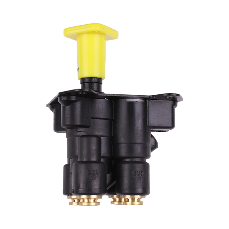
The brake foot valve is the core control element of the air brake system, converting the driver's mechanical input into precise air pressure output. The plunger (pushrod), a key component connecting the pedal to the piston inside the valve, dictates the precise height and free travel of the plunger, directly determining the brake system's response speed, progression, and overall safety. Even the slightest deviation can degrade brake system performance and even pose a safety hazard. Therefore, professional maintenance personnel must master the correct inspection and adjustment methods.
1. Inspection and Significance of Plunger Height
Plunger height refers to the distance from the top of the brake foot valve's main piston plunger to a reference plane (usually the mounting base or the cab floor). Correct plunger height ensures the valve remains in the fully closed position when the brake is not in use.
1. Inspection Method: Professional Gage and Reference Plane
Checking the pushrod height requires a professional depth gauge or vernier caliper:
Preparation: Ensure the vehicle's air pressure system is full, all brakes are released, and the pedal is in its fully released position.
Determine the reference point: The reference point is typically the flat surface of the fixing bolt holes in the foot valve mounting base, or a manufacturer-specified measuring point.
Measure: Place the reference surface of the gauge on the reference point and measure the vertical distance from the top of the pushrod to this reference surface.
Compare to Specifications: Compare the measured value to the technical specifications provided by the vehicle manufacturer (OEM).
2. Significance: Eliminate static leaks
If the pushrod height is too high, it may be preloading the internal piston, resulting in:
The exhaust valve may not fully open, potentially causing slight brake drag.
A slight push of the piston from its resting position can cause minor static leakage, resulting in a slow loss of system air pressure.
If the pushrod height is too low, the pedal free travel will be excessive, affecting brake response.
II. Free Travel Inspection and Criticality
Free travel refers to the distance the pushrod moves from the pedal's full rest position until it contacts or moves the internal piston, closing the exhaust valve. This is a key indicator of the driver's perception of "free travel" in the brake system.
1. Inspection Method: Precise Positioning and Marking
Inspecting free travel requires meticulous and precise operation:
Marking the Starting Point: Use a gauge to measure the distance (D1) from a fixed point on the brake pedal (treadle) in the full rest position to the cab floor.
Determining the Contact Point: Slowly and gently depress the pedal until you feel a slight change in resistance as the pushrod contacts or moves the internal piston in the valve. At this contact point, the brake system theoretically begins to close the exhaust valve.
Marking the contact point: Measure the distance (D2) from the pedal to the cab floor at the contact point.
Calculating free travel: Free travel (L) equals D1 minus D2 (L=D1−D2).
Comparison Specifications: Free travel must strictly adhere to the range specified by the OEM (usually a very small value, such as a few millimeters).
2. Criticality: Determines brake response speed and efficiency.
Excessive free travel: This results in no movement inside the valve during the initial pedal application. This causes a noticeable delayed brake response, which can be extremely dangerous in emergency situations.
Insufficient free travel (or no free travel): This means the push rod contacts or even slightly pushes the piston at the pedal's rest position. This can result in:
The exhaust valve cannot fully open, resulting in a slight, persistent brake drag.
Even slight vibrations or bumps can inadvertently trigger the brakes, compromising driving safety.
3. Professional Adjustment of Pushrod Height and Free Travel
Since the pushrod is directly connected to the pedal linkage, adjustment is typically achieved by changing the effective length of the pushrod itself or adjusting the stop bolt on the pedal linkage.
1. Adjustment Procedure: Gradual Approach and Repeated Measurement
Adjustment Mechanism: Many foot valve pushrods have an adjustable threaded connector or adjusting nut at the connection to the pedal.
Adjustment Goal: The primary goal of adjustment should be achieving the OEM-specified free travel. First, adjust the linkage length to achieve the correct free travel while ensuring that the pedal's full stroke can deliver the required output pressure.
Checking and Locking: After each adjustment, remeasure the free travel and pushrod height to ensure both are within specifications. After adjustment, securely lock the adjustment with the lock nut to prevent loosening during operation.
2. Common Mistakes to Avoid
Adjusting Only the Pedal Height: This incorrect adjustment focuses solely on the pedal height relative to the floor, ignoring the clearance between the pushrod and piston, which is the key factor in determining free travel.
Overadjusting: Making large adjustments at once, rather than making smaller, repeated adjustments and measurements, can easily exceed the safe range.
Ignoring Lubrication: Lack of lubrication in the pushrod-link mechanism can increase friction, potentially creating the illusion of "too little free travel," affecting measurement accuracy.


