What are the main components of the truck air brake system?
The truck air brake system is an important guarantee for the safe driving of large vehicles. It relies on compressed air to drive the brake device to achieve efficient and reliable braking effect. The system has a complex structure and is composed of a variety of professional components. The various parts cooperate with each other to ensure that the vehicle can brake stably under different working conditions.
Air compressor
The air compressor is the power source of the entire air brake system. Its main function is to use the engine power to compress the air, compress the air in the atmosphere to a high pressure state, and provide the system with the air source required for braking. The air compressor is usually driven by the engine crankshaft belt, with a sturdy structure and high working efficiency. The compressed air has a high pressure and temperature and needs to be processed later before it can be used.
Air dryer
The air dryer is installed between the air compressor and the air tank. Its main function is to remove moisture and oil from the compressed air to prevent ice and corrosion inside the system. If the moisture in the air is not removed in time, it will cause the brake line to freeze in cold weather, seriously affecting the braking performance. The air dryer contains a desiccant inside, which can effectively absorb moisture, and is equipped with an automatic drainage device to keep the air dry and clean.
Air tank
The air tank is used to store compressed air that has been dried to ensure that the brake system has a stable and continuous air supply when in use. The air tank is usually divided into a main air tank and an auxiliary air tank, and the capacity is determined according to the size of the vehicle and the braking demand. Condensation often accumulates inside the air tank and needs to be discharged regularly to prevent internal corrosion and blockage of the pipeline.
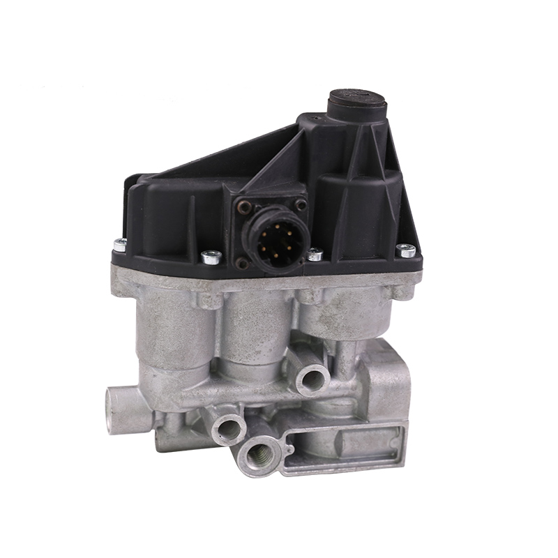
Brake valve (foot brake valve)
The brake valve is a key component for the driver to control air brakes. When the brake pedal is pressed, the brake valve adjusts the air pressure to the brake chamber, drives the brake mechanism to operate, and achieves vehicle deceleration or parking. The brake valve used in modern trucks usually integrates pressure feedback and multi-stage adjustment functions to ensure sensitive braking response and safety and reliability.
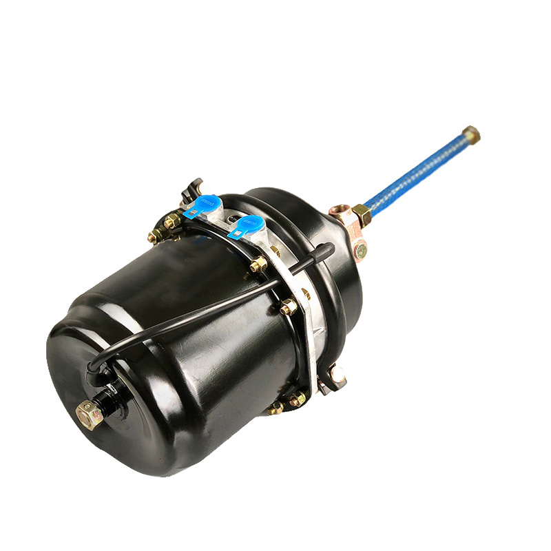
Brake air chamber
The brake air chamber is the core component that converts air pressure into mechanical force. A diaphragm or piston is arranged in the air chamber, which pushes the connecting rod after receiving the air pressure from the brake valve, and drives the brake shoe or brake pad to press the brake drum or brake disc. Brake chambers are divided into service brake chambers and spring brake chambers. The service brake chamber is mainly responsible for braking when the vehicle is driving, while the spring brake chamber is used for parking and emergency braking.
Spring brake chamber
The spring brake chamber is equipped with a strong preload spring, which uses the mechanical force of the spring to maintain the braking state. This component is mostly used for parking brakes to ensure that the vehicle does not slip when parking. After the engine is started and inflated, the air pressure will compress the spring and release the braking state. The safety performance of the spring brake chamber is extremely important, and the integrity and air pressure of the spring need to be checked regularly.
Brake connecting rod and regulator
The brake connecting rod transmits the thrust of the brake chamber to the brake mechanism to complete the conversion of air pressure to mechanical force. The regulator is responsible for automatically or manually adjusting the gap between the brake shoe and the brake drum to compensate for the wear of the brake shoe and maintain the braking efficiency. The automatic regulator can reduce the frequency of manual adjustment and improve the stability and safety of the system.
Brake line
The brake line includes the air pipeline connecting the compressor, air tank, brake valve and air chamber. The pipeline material must be resistant to high pressure, corrosion and cold, and is usually made of a combination of rubber hoses and steel hard pipes. Reasonable pipeline design can prevent air pressure leakage and mechanical damage, and is the basis for ensuring the air tightness and stability of the brake system.
Safety valve
The safety valve is installed at the air tank and key pipeline positions to prevent the system air pressure from exceeding the set upper limit. When the system air pressure rises abnormally, the safety valve automatically opens to release excess gas to avoid bursting of the air tank or pipeline and ensure system safety. The safety valve must be inspected regularly to ensure its reliability.
Auxiliary devices
The air brake system is equipped with a variety of auxiliary devices, such as barometers, air pressure alarms and pressure sensors. The barometer provides the driver with real-time air pressure information, and the air pressure alarm sounds an alarm when the air pressure is lower than the safety threshold, reminding the driver to deal with it in time. The pressure sensor provides data support for the vehicle's electronic control unit to ensure intelligent management of the system.
How does the brake chamber convert air pressure into mechanical force?
The brake chamber is a key actuator in the truck air brake system. Its core function is to convert the air pressure energy of compressed air into mechanical force, thereby driving the brake mechanism to slow down or stop the vehicle. The design structure and working principle of the brake chamber are directly related to the response speed of the brake system and the stability of the braking force.
Basic structure of the brake chamber
The brake chamber is mainly composed of a chamber shell, a diaphragm (or piston), a push rod and a spring. The chamber shell is made of solid metal material, and the interior is divided into two main spaces: the air pressure chamber and the spring chamber. The diaphragm is usually made of wear-resistant rubber material, with good sealing performance and can withstand repeated changes in air pressure. The push rod connects the diaphragm or piston to transmit the thrust generated by the air pressure to the brake mechanical part.
Functional distinction between the air pressure chamber and the spring chamber
The air pressure chamber is the part of the brake chamber that receives compressed air. Air enters the air pressure chamber from the brake valve through the pipeline, and the air pressure increases, pushing the diaphragm or piston outward. The spring chamber is equipped with a preloaded spring to provide reverse force and is used for parking brakes. When the air pressure is low, the spring force pushes the push rod back to the initial position and releases the brake state.
Working principle of air pressure conversion to mechanical force
When the driver steps on the brake pedal, the brake valve introduces compressed air into the air pressure chamber of the brake air chamber. The air pressure in the air pressure chamber rises rapidly, acting on the surface of the diaphragm to generate thrust. The magnitude of the thrust is proportional to the air pressure and the area of the diaphragm. The diaphragm expands outward under the action of air pressure, pushing the connected push rod to move axially. The movement of the push rod drives the connecting rod and the adjustment mechanism to convert the air pressure energy into mechanical force, which is applied to the brake shoe or brake pad to achieve the clamping of the brake drum or brake disc.
Mechanical transmission of push rod movement
The end of the push rod is usually connected to the brake connecting rod through a pin or a ball head. The axial movement of the push rod drives the brake mechanism to work. The brake connecting rod converts the linear motion of the push rod into the clamping motion of the brake shoe, forming friction and generating braking force. The distance the push rod moves determines the magnitude of the braking force, and a reasonable push rod stroke design ensures the linearity and sensitivity of the braking effect.
The difference between diaphragm and piston and their influence
The diaphragm structure in the brake chamber uses a flexible diaphragm to transmit air pressure thrust. It has a simple structure and light weight, and is suitable for light and medium trucks. The piston chamber uses a rigid piston instead of a diaphragm, which has better sealing and is suitable for heavy vehicles. The piston structure reacts faster to changes in air pressure, and the mechanical force transmission is more stable, which improves braking performance and reliability.
Special functions of spring brake chambers
The spring brake chamber is equipped with a large preload spring outside the air pressure chamber, which is often used for parking brakes. During normal operation, the air pressure compresses the spring, the push rod is in a loose state, and the brake is released. When parking or emergency braking, the system air pressure is cut off, the spring releases energy to push the push rod, and the mechanical force acts on the brake mechanism to lock the wheel and achieve parking brake. The spring brake chamber ensures that the vehicle can remain in a safe parking state even if the air source is interrupted.
Air tightness and response speed of the brake chamber
The air tightness inside the chamber directly affects the effective conversion and response speed of air pressure energy. Poor sealing will cause air pressure leakage, weaken the push rod pushing force, and increase the risk of brake failure. High-quality diaphragm materials and sealing design ensure that the brake chamber maintains good performance under extreme working conditions. The rapid air pressure charging and discharging process ensures rapid braking response and improves driving safety.
Maintenance and fault manifestations of brake chambers
Common faults such as ruptured brake chamber diaphragms, push rod jamming or spring fatigue can lead to brake failure or parking brake failure. Regularly checking the air tightness of the air chamber and detecting the push rod stroke and spring status are the key to ensuring the reliability of the brake system. Air pressure testing and leak detection can detect hidden dangers in advance and avoid driving accidents.
|
Long Stroke Brake Chamber |
|||||||||||||||||||||||||||||||||||||||||||||||||||||||||||||||||||||||||||||
|
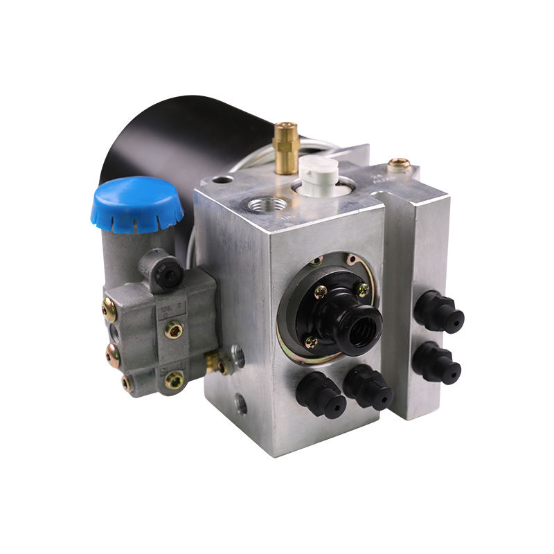
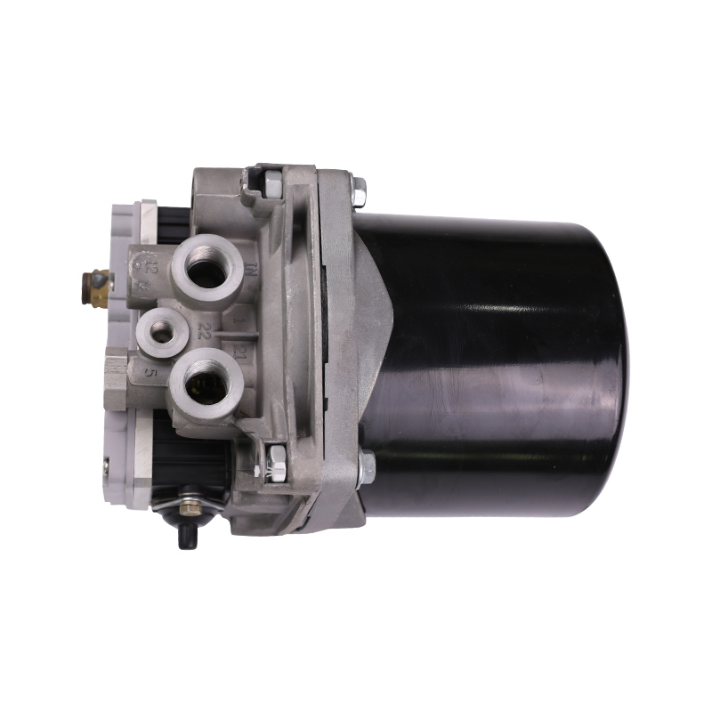
Why air dryers are important to air brake systems
Air dryers are an indispensable key component in truck air brake systems. Its main function is to remove moisture and impurities from compressed air to ensure the normal operation and long-term durability of the internal pipes and components of the brake system. The role of air dryers is directly related to the reliability, safety and maintenance cost of the brake system.
Moisture in compressed air and its hazards
The air brake system relies on an engine-driven air compressor to supply high-pressure air. After the air is compressed, the temperature rises, and the water vapor in the air begins to condense into water droplets during the cooling process. If these moisture are not effectively treated, they will enter the air tank and pipeline with the air, causing a variety of serious problems. Condensed water accumulates inside the pipeline and may freeze in a low temperature environment, blocking the air path and causing brake failure. Moisture can also cause rust and corrosion of internal parts of the system, reduce equipment life and cause leaks. Excessive moisture can also affect air pressure stability and cause insensitive brake response.
Working principle of air dryer
Air dryers are usually installed between the air compressor and the air tank. Its core part is a desiccant (such as silica gel or molecular sieve), which can efficiently absorb moisture from the air. When compressed air enters the dryer, moisture is absorbed by the adsorbent, and the air discharged after treatment remains dry and clean. Modern air dryers are mostly equipped with automatic drain valves to regularly discharge moisture and impurities accumulated in the adsorbent to prevent water accumulation and blockage, ensuring a long-lasting and stable drying effect.
Preventing ice failure in the brake system
In low temperature environments, moisture in the air pipeline is very easy to freeze, blocking the brake valve and air chamber, causing brake failure or even vehicle loss of control. Air dryers effectively remove moisture and prevent condensed water accumulation, greatly reducing the risk of ice blockage. Especially for vehicles traveling in cold areas or in winter, the importance of air dryers is particularly prominent, which directly guarantees the safety and stability of vehicle braking.
Protect key components of the braking system
The internal pipes, valves, air chambers and air tanks of the braking system are all precision machinery and sealing components, which are extremely susceptible to moisture erosion. Long-term water vapor intrusion can cause metal rust, aging of sealing rings, and valve jamming, affecting braking performance. Air dryers extend the service life of these key components by providing dry air, reduce failure rates and maintenance costs, and improve the overall operating efficiency of vehicles.
Improve system air pressure stability and response speed
Excessive moisture can cause air pressure fluctuations and leakage, affecting the air tightness and air pressure stability of the braking system. Air dryers can ensure that the air entering the air tank and pipelines is dry and pure, and ensure a stable supply of air pressure. Stable air pressure supports the efficient action of the brake chamber, improves the braking response speed and braking force, and improves driving safety.
Reduce maintenance difficulty and cost
Systems without air dryers or with poor drying effects require frequent drainage, cleaning of pipes, and replacement of corroded and damaged parts, increasing maintenance frequency and costs. Air dryers reduce manual intervention and maintenance workload by automatically dehumidifying and draining water. The system failure rate decreases, the vehicle running time increases, and the operating cost is significantly reduced.
Types and applicable scenarios of air dryers
Common air dryers include adsorption dryers and refrigerated dryers. Adsorption dryers absorb moisture through desiccant, have a simple structure, and are widely used in truck air brake systems. Refrigerated dryers condense and discharge moisture by lowering the air temperature, which is suitable for special environmental requirements. Different types of dryers are combined with the vehicle operating environment and working conditions to select the appropriate model to ensure the best drying effect.
Key points for maintenance of air dryers
Desiccant needs to be replaced regularly to prevent saturation failure of desiccant. The drain valve function needs to be maintained normally to ensure timely removal of condensed water and impurities. The air dryer housing and interface should be checked for leaks and good sealing performance. Improper maintenance will cause the dryer to fail, which in turn affects the safety performance of the entire brake system.
|
Brake System Air Dryer |
|||||||||||||||
|
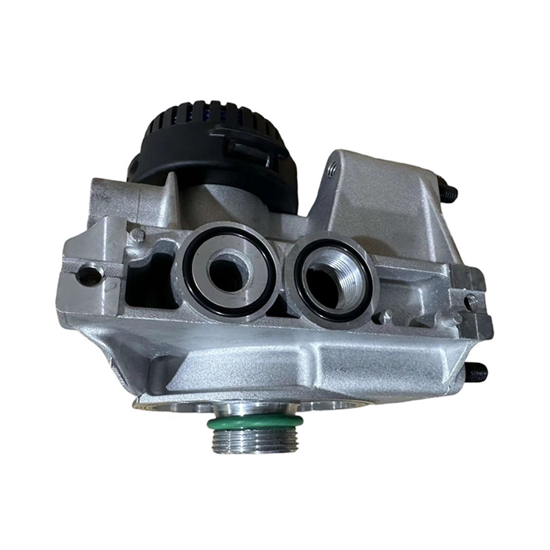
How does the brake valve (foot valve) control the brake air pressure?
The brake valve, also known as the foot brake valve, is a key component in the truck air brake system where the driver directly controls the brake air pressure. Its main function is to accurately adjust the air pressure according to the force and stroke of the driver's foot on the brake pedal, and drive the brake chamber to achieve vehicle braking. The design and working principle of the brake valve directly affect the response speed, stability and safety performance of the brake system.
Basic structure of the brake valve
The brake valve is mainly composed of a valve body, a piston or a sliding valve, a spring, a sealing ring and an adjustment mechanism. There are multiple air passages inside the valve body, which are responsible for guiding the air flow. The piston or sliding valve moves under the action of the spring force and air pressure to control the air flow interruption. The brake pedal drives the piston to move through a mechanical connecting rod or an electronic sensor to complete the air pressure regulation.
Working principle of the brake valve
When the driver steps on the brake pedal, the piston inside the brake valve moves forward with the pedal stroke. The movement of the piston changes the opening and closing state of the air circuit inside the valve body, and controls the air from the air tank to the air pressure chamber of the brake chamber. The deeper the pedal is stepped on, the larger the valve opens, and the higher the air pressure entering the brake chamber. The increased air pressure pushes the brake chamber diaphragm or piston, generating a mechanical thrust to achieve braking. Release the pedal, the piston resets, the air circuit is closed, the air pressure is released, and the brake is released.
Precise control of brake air pressure regulation
The brake valve achieves continuous variable adjustment of air pressure through an internal adjustment mechanism. The valve body is designed with a pressure adjustment spring and a feedback device, which can finely adjust the output air pressure according to the pedal force. Accurate air pressure control ensures a smooth transition of braking force, avoids braking shock and vehicle shaking, and improves driving comfort and safety.
Multi-way air circuit design and safety guarantee
The brake valve is equipped with multiple air circuits, which lead to different air tanks and air chambers to ensure stable air pressure supply. Some brake valves are equipped with a dual-circuit design, one circuit controls the front axle air chamber and the other controls the rear axle air chamber to improve braking safety. Some advanced brake valves also have an air pressure protection function. When the system air pressure is lower than the set value, the braking force is automatically limited to prevent brake failure.
Response speed and sealing performance of brake valve
The internal sealing ring and air circuit design of the brake valve directly affect the response speed of air pressure changes. Efficient sealing prevents air leakage and ensures stable air pressure. The brake valve with a compact structure and reasonable spring force can quickly respond to the driver's braking command, achieve rapid braking response, and enhance driving safety.
Coordination of foot brake valve and parking brake system
The foot brake valve is mainly responsible for service braking during driving. The brake valve of some models integrates the parking brake function or is linked with the parking brake valve. The spring brake chamber is controlled by air pressure changes to realize the opening and release of the parking brake. The system design ensures that the parking brake and foot brake work together to meet different driving needs.
Maintenance and failure manifestations of brake valves
Aging of brake valve seals, piston jamming or spring failure are common causes of failure. This leads to insensitive air pressure regulation, air leakage or uneven braking. Regularly check the air tightness, pedal travel and internal component status of the brake valve to ensure its normal performance. If a fault is found, it should be repaired or replaced in time to avoid safety hazards.
What role does the safety valve play in the air brake system?
The safety valve is a vital protective component in the air brake system. It is responsible for releasing excess air pressure when the system pressure rises abnormally, preventing system components from being damaged by overpressure, and ensuring the safety and stable operation of the entire brake system. Although the safety valve does not directly participate in the braking action, it plays an important role in the operation of the system.
The basic structure and principle of the safety valve
The safety valve is usually composed of a valve body, a valve seat, a spring, a valve core and an adjustment mechanism. The valve core seals the valve seat under the action of the spring force to maintain the closed state of the system. The spring preload sets the maximum safe air pressure of the system. When the system air pressure exceeds the set value, the air pressure overcomes the spring force to push the valve core open, and the overpressure gas is released through the exhaust port. After the air pressure drops to a safe range, the spring resets the valve core, reseals the valve seat, and the system returns to normal working state.
Control the upper limit of air pressure to prevent system overpressure
The air brake system is supplied with air by an air compressor. If the control system fails or the compressor continues to work without stopping, the air pressure may continue to rise. Overpressure can damage and even burst components such as air reservoirs, brake valves, pipelines, and air chambers. The safety valve opens the exhaust in time before the air pressure reaches a dangerous level through the set opening pressure (usually 10%~15% of the upper limit of the system working pressure), playing the role of "the last line of defense" to avoid system damage and accidents.
Protect the air compressor and air circuit components
The air compressor is a high-frequency component in the brake system, and it is very easy to be damaged due to excessive back pressure during long-term operation. The safety valve releases excess air pressure in the system compression chamber or the main air tank, effectively reducing the compressor load and preventing problems such as shaft seal damage and cylinder jamming caused by back pressure. At the same time, the safety valve also protects the pipeline interface and air circuit valve to avoid impact rupture caused by sudden pressure changes and extend the service life of the system.
Ensure the stable function of the vehicle braking system
The air brake system must operate in a stable air pressure environment. Excessive air pressure not only damages the components, but also causes excessive braking response and excessive braking force, causing tire locking and vehicle loss of control. The safety valve limits the peak pressure and keeps the system pressure within a safe range, ensuring that the braking response is linear and controllable, and enhancing the driver's sense of safety and predictability.
The rationality of the set pressure value and the system match
The opening pressure of the safety valve should be higher than the normal working pressure of the brake system (usually 0.81.0 MPa), but lower than the maximum pressure bearing capacity of the system. It is generally set to 1.11.2 MPa. If the pressure is set too low, it is easy to open frequently and cause unstable air pressure; if it is set too high, it loses its protective effect. Reasonable setting requires comprehensive consideration of factors such as vehicle air path volume, braking frequency, and compressor air output to ensure that the safety valve intervenes only under real overpressure conditions, taking into account safety and system efficiency.
Installation location and scope of action of the safety valve
The safety valve is usually installed on the main air tank or the main line of the total air path, giving priority to releasing the total pressure of the system. Some systems are also equipped with local safety valves on branch air tanks or independent air paths to protect branch circuit components. The installation location should ensure smooth exhaust and stay away from high temperature or flammable areas to prevent secondary risks caused by exhaust. The multi-level protection design enhances the robustness of the system and improves the safety level of the vehicle.
Material and durability requirements of safety valves
Safety valves are subjected to high-pressure gas for a long time, and key components such as valve cores, springs, and valve seats must have high strength, corrosion resistance, and fatigue resistance. Common materials include stainless steel, chromium-molybdenum alloy, engineering plastics, etc. The sealing part must have high temperature resistance and pressure change resistance to ensure that the valve remains sealed reliably during high-frequency opening and closing to avoid air pressure leakage or malfunction.
Maintenance inspection and failure risk of safety valves
Safety valves are passive action devices. Long-term non-operation is prone to problems such as spring fatigue, valve core jamming, and seal aging. Regular opening and closing tests, cleaning of carbon deposits and foreign matter, and testing of opening pressure are necessary means to maintain its functional reliability. A failed safety valve may not be able to open when overpressure occurs, resulting in system damage or accidents; it may also open prematurely, affecting the inflation speed and efficiency of the brake system.
Cooperation between safety valve and pressure regulation system
Air brake systems are usually equipped with pressure regulators, pressure switches, and safety valves that work together. The pressure regulator controls the start and stop of the compressor, the pressure switch monitors the air pressure feedback, and the safety valve is used as a redundant protection device to ensure that multiple safety mechanisms are effective. The design and adjustment of the safety valve should be coordinated with the entire air pressure control system to avoid false triggering or overlapping functions and improve the overall safety of the system.
What are the daily maintenance priorities of the air brake system?
As a critical safety device in heavy vehicles (such as trucks, buses, and trailers), the operating stability of the air brake system is directly related to the braking effect and traffic safety of the entire vehicle. The system consists of an air compressor, an air reservoir, a dryer, a brake valve, a brake air chamber, an air pipe, and a variety of control components. It has a complex structure and operates frequently. Scientific and standardized daily maintenance can not only extend the life of the system, but also effectively prevent sudden brake failures.
Check the air tightness of the system
The air tightness of the system is the core of ensuring stable air pressure. During maintenance, it is important to check whether there is air leakage at various pipe joints, hoses, connectors, welds of air reservoirs, and valve body interfaces. Use soapy water smearing method or a special leak detector to detect subtle leaks. For rubber hoses, check whether they are aging, cracked, or falling off. Good air tightness can prevent the system air pressure from dropping too quickly, ensuring the reliability of emergency braking and parking brakes.
Regularly drain water and impurities from the air tank
The air tank is a gathering place for compressed air and is also the main area for condensed water and impurities to deposit. If it is not discharged in time, the water will corrode the cylinder, block the valve, and seriously affect the braking response. The air tank drain valve should be opened every day after parking to drain manually, especially in an environment with high humidity or low temperature. Some vehicles are equipped with automatic drainage devices, and their drainage function should also be checked regularly to prevent water accumulation.
Check the working condition of the air dryer
The air dryer is the first line of defense to prevent moisture from entering the brake system. It is necessary to regularly check whether the dryer filter element or adsorbent is saturated and ineffective. If it is found that the drying effect has deteriorated or a large amount of water is discharged from the air tank, the dryer filter element should be replaced in time. Note that the dryer exhaust port should be unobstructed and the exhaust valve should be sensitive to prevent water accumulation or freezing.
Keep the brake valve responsive
The brake valve is the most directly related component of the air brake system to the driver's control. The brake valve pedal stroke should be checked regularly to see if it is appropriate, if the action is smooth, and if there is any jamming, air leakage or poor return. Check if the air chambers respond consistently during braking to avoid brake deflection or tail swinging due to asynchronous braking of the front and rear wheels. Disassemble and clean or replace seals if necessary.
Check the brake chamber and push rod status
The brake chamber converts air pressure into mechanical braking force, and its reliability directly affects the braking effect. Focus on checking whether the air chamber shell is deformed, rusted or cracked, whether the push rod is freely retracted, and whether the dust cover is intact and undamaged. The spring mechanism of the parking brake spring chamber must function normally and the exhaust channel must be unobstructed. The push rod stroke must meet the manufacturer's standards to avoid insufficient braking force or damage to the air chamber.
Maintain the air pipe and joint connection firmly
The air pipe connecting the various components in the brake system needs to have sufficient pressure resistance and heat resistance. Check the pipeline for looseness, detachment, rupture, expansion or wear on a daily basis. In particular, the hoses at the chassis or active parts of the vehicle are susceptible to vibration and dust. The connection joints should be tightened reliably, and the quick-connect joints should be cleaned of foreign objects regularly to prevent leakage. Pipes used for a long time should be replaced according to the degree of aging.
Check the emergency brake and parking brake system
Emergency brake and parking brake are important mechanisms to ensure that the vehicle can still stop reliably when the gas is cut off or the engine is turned off. Daily maintenance should verify whether the spring brake air chamber can automatically apply the brake when the gas is cut off. The parking lever or switch should be accurate and sensitive. The parking pressure maintenance capacity after the system is cut off must meet the standard to prevent the vehicle from sliding due to air pressure leakage.
Detection of pressure gauge and alarm device
The pressure gauge on the instrument panel is an important basis for the driver to understand the system status. It is necessary to confirm that the pressure gauge display is accurate and without deviation on a daily basis. The high-pressure and low-pressure alarm indicators and buzzers should alarm in time when the air pressure is abnormal. If necessary, check the working status of the electrical circuit and sensor to avoid blind driving caused by the failure of the alarm system.
Perform system air pressure stability test
Observe the air pressure build-up speed by running the engine at idle speed and check whether the compressor output is sufficient. The system should maintain the pressure drop speed after the engine is turned off to meet the standard. The brake response time and pressure drop rate can be observed by manually stepping on the brake pedal to judge the system response capability and air storage capacity.